Transfer Function|
Example of Deviation for a Step-up Converter
2018.01.11
Points of this article
・For both types of converter, what are derived are Δvout/ΔD and ΔiL/ΔD.
・Transfer functions are derived in two steps--by considering the stable states of the system, and then by determine the amount of change given for an external disturbance.
・In this section, we derived the transfer functions for a step-up converter, but the approach was entirely the same as the derivation for a step-down converter.
In succession to the previous discussion of step-down converters, this time we present a derivation example for step-up converters. Please refer to the previous section as necessary.
Example of Transfer Function Derivation for Step-up Converters
This time, we shall derive the transfer functions for a step-up converter. But as with a step-down converter, the transfer functions to be derived are ![]() and
and ![]() . When deriving the transfer functions for step-down converters, the following two steps were taken; and when addressing step-up converters as well, we resort to the same steps for our derivation of the transfer functions.
. When deriving the transfer functions for step-down converters, the following two steps were taken; and when addressing step-up converters as well, we resort to the same steps for our derivation of the transfer functions.
●Step 1: Consider the stable states of the system
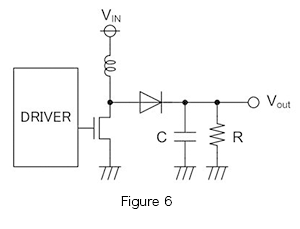
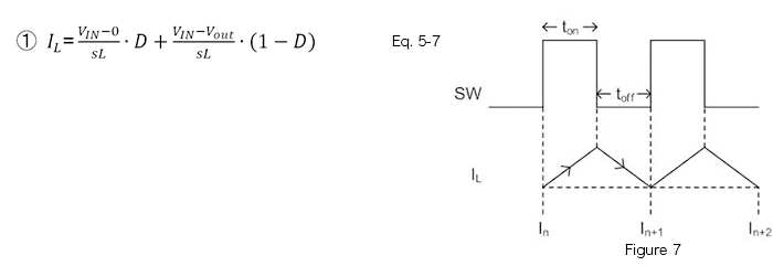
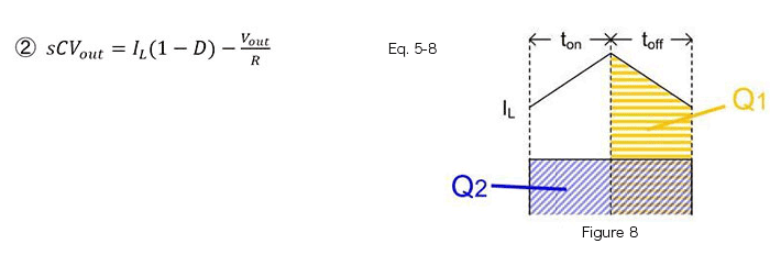
The procedure is similar to that for the step-down converter. Figure 6 is the basic circuit of a diode-rectified step-up converter. The stable states of the system are the following two states; each is represented by an equation and a graph.
① The coil current does not change over one period
② The capacitor charge amount does not change over one period
●Step 2: Determine change amounts for an external disturbance, and describe the transfer functions
Calculation examples are shown below.
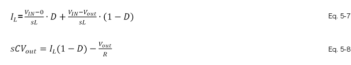
Upon substituting ![]() in equations 5-7 and 5-8, the following are obtained.
in equations 5-7 and 5-8, the following are obtained.
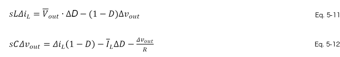
Then, taking equations 5-11 and 5-12 to be simultaneous equations and determining ![]() and
and ![]() , we obtain the following.
, we obtain the following.
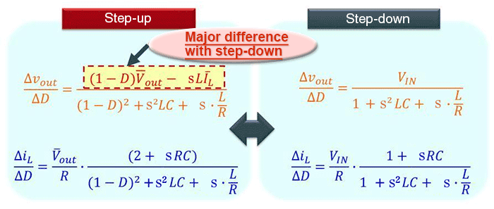
For the sake of comparison, the transfer functions have been provided along with those for step-down converters. Of course, the derivation results are different, but what should be noted here is that the same approach as with the step-down mode is used for the step-up mode as well to derive ![]() and
and ![]() .
.
Transfer Function
- What are transfer functions?
- What is the Transfer Function of an Amplifier?
- What is the Transfer Function of a Slope?
- What is the switching transfer function?
-
Transfer function of each converter
- Example of Derivation for a Step-Down Converter
- Example of Deviation for a Step-up Converter
- Example of Derivation for a Step-Up/Step-Down Converter – 1
- Example of Derivation for a Step-Up/Step-Down Converter – 2
- Switching Transfer Functions: Derivation of Step-down Mode Transfer Functions Serving as a Foundation