Glossary
Principles of Operation of Boost DC-DC Converters
2025.04.18
About Boost DC-DC Converters

Boosts a low voltage to a high voltage
A boost DC-DC converter is an electronic circuit that converts from DC (direct current) to DC, but outputs a voltage that is higher than the input voltage (that is, boosts the voltage). For example, by using a boost DC-DC converter, a high voltage can be obtained even from the low voltage of a battery power supply.
Moreover, there are also buck DC-DC converters that output voltages lower than the input voltage. DC-DC converters are vital electronic circuits that can produce voltages either higher than or lower than the input voltage.
Various electronic devices which handle various DC voltages have been developed, and the power supplies needed for these devices likewise vary greatly. Hence DC-DC converters that can convert an input to the required voltage are also used in numerous devices.
ICs and other semiconductor devices often operate at low voltages such as 5 V or 3.3 V, and so in general a power supply is chosen that can output a higher voltage than the electronic circuit, and a converter is used that lowers (steps down) the voltage.
Differences Between Linear Regulators and Switching Regulators
DC-DC converters are classified as either linear regulators or as switching regulators according to differences in the conversion method used.
A linear regulator is a device in which a control element is inserted between the input and the output, in such a way as to step down the voltage. It has a simple configuration using series connections, and so the simplicity of the circuit is one feature. However, when the control element steps down the voltage, heat is generated, and current is consumed; thus linear regulators have the drawback of poor conversion efficiencies of around 30 to 50%, or at most 70%.
Moreover, the higher the step-down ratio between the input and the output, the more heat is generated, and not only does efficiency suffer, but measures to deal with heat also become necessary. Measures to cope with heat include promoting the escape of heat from the housing and installing a heat sink to improve heat dissipation. In consideration of conversion efficiencies and heat generation issues, linear regulators are better suited to power supplies for loads requiring less power.
Switching regulators differ from linear regulators in being capable not only of stepping down voltages, but also of various other conversions such as boosting and inverting voltages (negative voltages). Using switching elements, these devices turn on the switch until the required output voltage is reached to supply power, and when the output voltage reaches the required value, turn off the switching element. By repeating switch turn-on/off, the voltage is adjusted.
In contrast with heat-generating linear regulators, conversion by switching results in a high conversion efficiency of around 90%, and in addition to the satisfactory efficiency, there is the further advantage that minimal heat is generated.
However, because noise occurs due to the switching operation, a design to address noise is needed. Moreover, apart from the switching element, coils, capacitors, and other external components are also necessary, and together with the measures to deal with noise, there is the disadvantage that the device design tends to be complex. However, in recent years, switching ICs have appeared that incorporate required components such as coils and capacitors, making circuit design easy.
Because a switching regulator circuit that generates little heat can be built, switching regulators are well-suited to the power supplies of digital circuits requiring low voltages and large currents.
*In this article, voltage boost is explained, and so “DC-DC converters” here means switching regulators.
Applications for DC-DC Converters
DC-DC converters are widely used in all kinds of electrical products and systems. For example, it is safe to say that they are in use in entire lineups of home appliances and electrical products, among them personal computers, washing machines, game consoles, electric automobiles, and so on.
Homes are equipped with electrical outlets enabling use of an AC 100 V power supply, but electrical products are not necessarily using the 100 V alternating current as-is. Inside many products the 100 V alternating-current power supply is converted to a direct-current power supply, which is then boosted or stepped down in voltage by a DC-DC converter before being supplied to various circuits.
In the case of a notebook computer, for example, an AC adaptor is plugged into an outlet to power the device. The notebook computer has an internal battery in addition to the AC adapter, and the battery must be charged. There is also a CPU, memory devices, and other integrated circuits, as well as a display, disk drive, and a keyboard, mouse, and possibly other input devices. Because the product includes such a variety of devices, different voltages must be applied to each of them. For this reason, a DC-DC converter boosts the power supply voltage or steps down according to the different devices used. This enables each of the different devices to function normally when the notebook computer is running.
And it’s not just notebook computers; many electric products incorporate electronic circuits, prominent among them integrated circuits, and are operating using internal DC-DC converters. It should be noted however that there are also some products that use the electric power for heating, such as toasters and electric space heaters, and these use the 100 V alternating current without modification–that is, they do not include DC-DC converters.
Voltage Boost Operating Principles
Here we explain the principles of operation of boost DC-DC converters (switching regulators). The basic configuration is not very hard to understand; voltage boost is performed using an input power supply, a coil, a switch, and an output capacitor.

Raising a Voltage Using the Properties of a Coil
In order to boost a voltage, the properties of a coil are used. When a rapid change in the current flowing in a coil occurs, a force acts so as to maintain the original state.
A switch is connected in the circuit such that, when the switch is turned on, the state changes from the original state in which no electricity was flowing to a state of flowing current; the above coil property causes it to accumulates energy so as to keep current from flowing, and causes more than a certain amount of electricity not to flow. When, conversely, the switch is turned off, causing electricity not to flow, the energy that had accumulated is released, and an action (a high voltage) appears, higher than the original voltage, acting to cause electricity to flow.
A boost DC-DC converter uses this high voltage that occurs when the switch is changed from the state in which current is flowing (the switch on state) to when the switch is turned off. By rapidly switching the switch on and off, a higher voltage than the original voltage can be created.
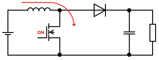
Operation When the Switch Is Turned On
When the switch is turned on, current flows from the input power supply through the coil to the switch. If electricity continues to flow in this way it will increase, but because the coil acts to impede an increase in current, energy is accumulated in the coil.
Operation When the Switch Is Turned Off
When the switch is switched to off, because the coil has the property of trying to keep current flowing without change, a high voltage is created, and the coil releases the energy that had accumulated in the coil up to that time. The discharged current flows into the capacitor, which is charged.
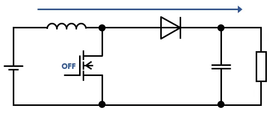
While the switch is turned on, electricity increases in the coil, and at the instant the switch is turned off, energy accumulated in the coil is released and a voltage higher than that of the input power supply charges the capacitor. In this step, if the switch turn-on/turn-off is repeated, the voltage can be raised to a desired level.
When a voltage is to be converted into a high voltage, a capacitor with a large capacitance is necessary. As the switching element, a semiconductor device such as a transistor or MOSFET is used.
How High Does the Output Voltage Rise?
One question to ask ourselves is how high the output voltage can be raised. This question should be considered when designing a circuit, so it is here addressed.
We consider the amount of change in current while the switch is turned on. If the voltage across the coil is VIN, the time over which the switch is turned on is TON, and the coil inductance is L, then the increase in current while the switch is turned on is expressed as follows. The longer the time TON over which the switch is turned on, the greater the increase in current flowing in the coil.
\(I_{ON} = \displaystyle \frac{1}{L} \times V_{IN} \times T_{ON}\)
Next, let us consider the change in current while the switch is turned off. When the switch is turned off, energy accumulated in the coil is released, and so the coil current decreases. The amount of current decrease is expressed by the following equation.
\(I_{OFF} = \displaystyle \frac{1}{L} \times (V_{OUT} – V_{IN}) \times T_{ON}\)
The voltage rises accordingly as the current increase while the switch is turned on and the current decrease while the switch is turned off are the same. Hence an equation to calculate VOUT when ION and IOFF are equal can be derived as follows.
\(V_{OUT} = \displaystyle \frac{T_{ON} + T_{OFF}}{T_{OFF}} \times V_{IN}\)
The Greater the Step-up Ratio, the Lower Is the Maximum Output Current
We have seen how the voltage increases in a voltage boost operation; now we will look at what happens to the output current. Let the average current supplied from VIN during the time the switch is on (until it is switched off) be IIN, and let the current output from VOUT while the switch is off be IOUT. The power is found by computing voltage (V) × current (I), so the following equation obtains.
\(V_{IN} \times I_{IN} = V_{OUT} \times I_{OUT}\)
Hence we see that if the output voltage is raised by voltage boost, the output current, in contrast, falls.
For example, consider a case in which the input voltage (VIN) is 5 V and the input current (IIN) is 20 A. The output current (IOUT) is found from the following equation.
\(I_{OUT} = \displaystyle \frac{V_{IN} \times I_{IN}}{V_{OUT}}\)
If the output voltage is 10 V, then \(I_{OUT} = \displaystyle \frac{V_{IN} \times I_{IN}}{V_{OUT}} = \displaystyle \frac{5 \times 20}{10} = 10\)
If the output voltage is 20 V, then \(I_{OUT} = \displaystyle \frac{V_{IN} \times I_{IN}}{V_{OUT}} = \displaystyle \frac{5 \times 20}{20} = 5\)
If the output voltage is 25 V, then \(I_{OUT} = \displaystyle \frac{V_{IN} \times I_{IN}}{V_{OUT}} = \displaystyle \frac{5 \times 20}{25} = 4\)
From the above, we see that the more the output voltage is increased (the greater the boost voltage ratio), the greater is the drop in output current. In the above equations, conversion efficiency is not considered, but if the conversion efficiency is included, the output current drops even more.
Understanding the Operating Principles of Voltage Step-up
In this article, we have explained how voltage boost is performed by DC-DC converters. There are two types of DC-DC converters–linear regulators and switching regulators–but only switching regulators are capable of voltage boost. And because of their high efficiency, switching regulators are used in many electric circuits.
A switching regulator uses the properties of the coil to boost a voltage. However, it must be noted that as the boost ratio increases, there is the drawback that the maximum output current decreases.
The mechanisms of voltage boost and step-down are fundamental to an understanding of electronic circuits. Thus it is important to obtain a thorough understanding of coil properties and the operating principles of voltage boost operations.
【Download Documents】 Switching Regulator Basics
The basics of step-down switching regulators, including their operation and functions, are explained. Comparison with linear regulators, synchronous rectification and diode rectification, control method, auxiliary functions, etc. are also explained.

Glossary
-
Evolving Semiconductor Wafer Technology
-
What is the Structure of a Motor? | The Principle and Mechanism of Rotation, and Reasons for Widespread Use
-
What are semiconductor raw materials?
-
What is Conducted Noise? Its Types and Countermeasures
-
What Is Tjmax? Thermal Resistance and Thermal Design
-
Power MOSFET in Relation to DMOS
-
What Is Ringing? Problems with Switching Power Supplies and Countermeasures
-
Principles of Operation of Boost DC-DC Converters
-
Converting from 24 V to 12 V? Understanding DC-DC Converters