Diodes|Basic
Zener Diode
2026.06.17
A Zener diode (often called a “constant-voltage diode”) is a semiconductor device that maintains a stable voltage across the diode when reverse bias voltage rises above a certain breakdown voltage. It exploits what is known as “Zener breakdown” (or “Zener effect”), which a normal diode typically does not exhibit. For instance, in a power supply or sensor circuit, a Zener diode can protect against transient voltage spikes, stabilize the output voltage, and even serve as a simple voltage regulator. Here, we will explore how a Zener diode operates, how it provides a regulated voltage across its terminals, and how it can provide overvoltage protection, low-power voltage references, and more.
The Basics of Zener Diodes
To fully understand why a Zener diode exhibits unique reverse breakdown voltage characteristics, it helps to compare it with a conventional diode and then examine the internal structure and variations of Zener-type diodes. These diodes can clamp an input voltage to the rated Zener voltage (the so-called Zener breakdown region), thereby playing multiple roles in electronic circuits, from load-voltage stabilization to overvoltage protection.
Definition and Core Principle of Zener Diodes
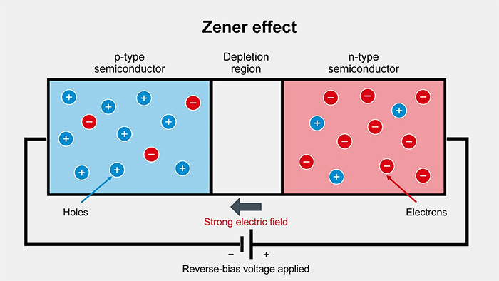
A Zener diode is specifically designed to allow current to flow in the reverse direction once the reverse voltage exceeds a certain breakdown diode threshold. This threshold is known as the Zener breakdown voltage. When the reverse bias voltage across the diode exceeds the Zener breakdown voltage, the depletion region inside the pn junction collapses, allowing current to flow while keeping the voltage across the diode nearly constant. In practice, this means that if a power supply or another circuit node accidentally exceeds the Zener diode’s rated voltage, the Zener diode conducts heavily in reverse, limiting the voltage drop to its stable voltage.
Zener diodes take advantage of the high electric field inside a heavily doped pn junction, where the Zener effect becomes dominant. This behavior is distinct from that of a normal diode, which typically fails destructively under a large reverse voltage. The unique property of the Zener diode is its ability to remain operational even under high reverse voltage, maintaining a consistent voltage across its terminals.
How They Differ From Conventional Diodes
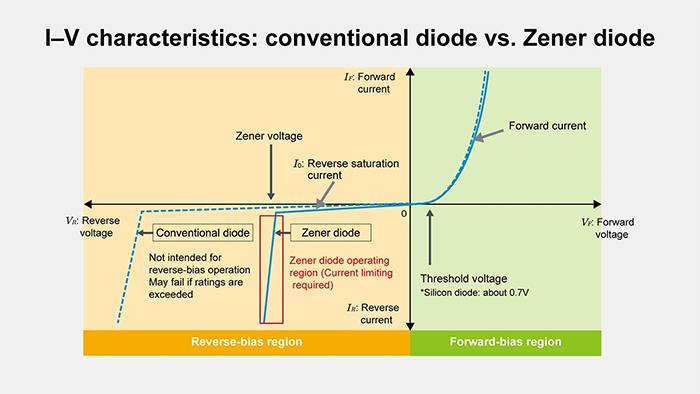
A conventional diode allows current to flow primarily in the forward-biased diode direction (from the anode to the cathode). It blocks current in the reverse direction until breakdown occurs, typically destroying the diode. By contrast, a Zener diode is intentionally designed so that when reverse bias voltage exceeds its rated Zener voltage, the diode not only survives but also remains in a stable breakdown region. In other words, a normal diode is not designed to hold a stable voltage across it in reverse breakdown, while a Zener diode regulates voltage in reverse bias.
In forward bias, a Zener diode behaves much like a normal diode, showing a forward voltage drop of about 0.7 V in a silicon-based design (though the exact knee voltage may vary). The critical difference is that the Zener diode is optimized to clamp a reverse-bias voltage at a stable value once Zener breakdown occurs, offering a built-in voltage regulator or voltage shifter effect in many electronic circuits.
The Working Principle of Zener Diodes
What really makes a Zener diode special is how it allows current to flow in the reverse direction while keeping the voltage across it nearly constant. In this section, we discuss the differences between Zener breakdown and avalanche breakdown, how reverse bias voltage leads to a stable voltage regulator effect, and the actual mechanism by which the diode clamps the reverse voltage at a set point.
Zener Effect vs. Avalanche Breakdown
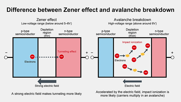
When a reverse bias voltage rises high enough, the diode enters a breakdown region where a large current can flow. In many Zener diodes below about 5–6 V, the Zener effect dominates. This effect relies on quantum tunneling in a heavily doped pn junction, causing current to flow sharply at the knee voltage with minimal increase in diode voltage.
Above about 6 V, avalanche breakdown occurs, in which carriers gain sufficient energy from the electric field to create additional electron-hole pairs (impact ionization). This avalanche breakdown region also clamps the reverse voltage at a stable level. In practice, typical Zener diodes in the 5–6 V range (or lower) rely primarily on the Zener effect, while higher-voltage diodes rely largely on avalanche breakdown. Regardless of which phenomenon predominates, we generically refer to both as “Zener breakdown” because the diode is sold and specified as a Zener diode.
Reverse Bias Clamping Operation
A Zener diode “turns on” in reverse when the reverse voltage exceeds the Zener breakdown voltage. Before that point, the current flowing in the opposite direction (reverse direction) remains extremely small. Once the diode enters the Zener breakdown region, even if the reverse voltage increases further, the voltage across the diode itself does not rise substantially. Instead, more current flows through the diode, clamping the voltage across the diode to roughly the rated Zener voltage.
This property is valuable when overvoltage protection is required. If a circuit experiences a high reverse-voltage spike, the diode enters breakdown, channeling current safely away to maintain a stable voltage. Because the current can be quite large, the diode’s maximum power rating must be observed, or else excessive power dissipation may damage the diode.
Voltage Regulation Behavior
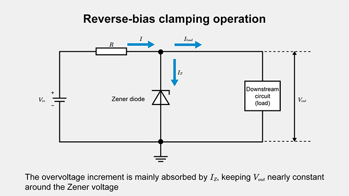
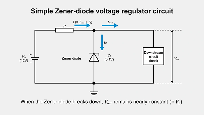
One popular use of a Zener diode is to establish a stable output voltage in a power supply circuit with minimal components. By placing a Zener diode in reverse bias across a load, along with a series resistor to control the current, you can maintain a nearly constant output voltage equal to the Zener diode’s rated voltage. Suppose you have a 5.1 V Zener diode and want to generate a stable 5.1 V from a 12 V input supply. You add a series resistor, choosing its value so that the current flowing through the Zener diode (plus the load current) remains sufficient for regulation but does not exceed the diode’s maximum current rating.
For example, with an input voltage of Vin and a Zener voltage of VZ, the series resistor R is typically chosen by:
\(R = \displaystyle \frac{V_{\text{in}} – V_{\text{Z}}}{I}\)
where III must at least be the minimum current required to keep the diode in regulation, plus any load current you anticipate. Such a Zener voltage regulator arrangement is straightforward. Still, it may waste power in the resistor and diode when the input voltage or load current is high, so it’s usually used for low-power or reference-level regulation.
Major Applications of Zener Diodes
Zener diodes are found in a variety of electronic circuits thanks to their ability to clamp reverse voltage or provide a stable output voltage. From over-voltage protection to creating stable voltage references, these diodes play many different roles. Let’s look at some prime examples of how Zener diodes are employed in practical designs.
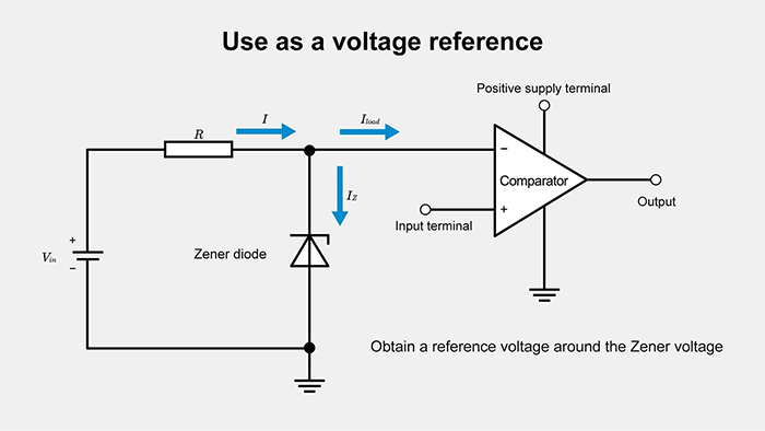
Using Zener Diodes as a Voltage Reference
One of the most direct applications is generating a stable reference voltage for analog circuits. A Zener diode set to break down at a specific knee voltage can act as a fairly consistent reference, so that the load voltage or comparator thresholds remain steady even if the power supply or input signal flutters slightly. While a Zener diode does not offer the same ultra-precise temperature stability as specialized voltage reference ICs, it is a simple, cost-effective way to get a few volts of stable reference in many electronic circuits.
Keep in mind that the temperature coefficient can shift the breakdown voltage with changes in temperature. Designers should account for it if the application demands close voltage tolerance. Also, a small, constant current is generally needed to maintain regulation, so the total power dissipation must be balanced against the circuit’s objectives.
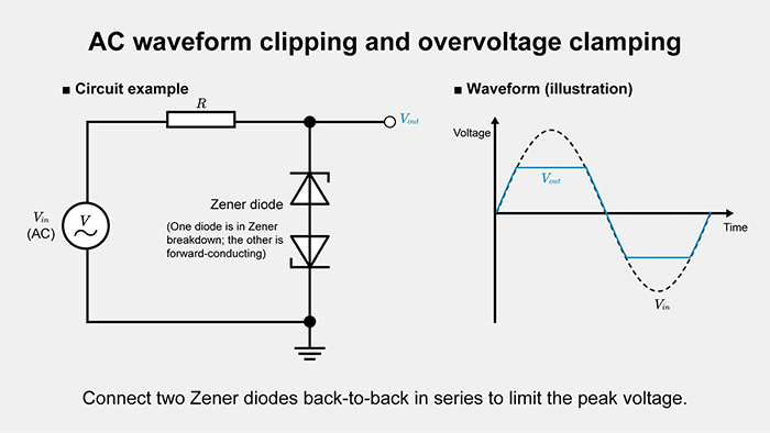
AC Waveform Clipping and Overvoltage Clamping
Zener diodes also appear in circuits that require waveform shaping—specifically, clipping or clamping an AC waveform or pulses to a given level. For instance, in audio circuits, you can shape overdriven guitar signals or prevent signal amplitude from surpassing a threshold by wiring two Zener diodes in opposite directions. This configuration ensures that the signal does not exceed a certain positive or negative swing.
Such clipping behavior is also practical for overvoltage protection of signal lines. Once the input signal rises above (or falls below) the Zener diode’s rated breakdown region, the diode starts conducting, clamping the amplitude. This approach is also helpful in digital and communications circuits where you want to ensure the input signal never exceeds the device’s absolute maximum rating.
For surge protection, a Zener diode is placed in parallel with the supply or signal line. Under normal conditions, the diode is nearly invisible (extremely high impedance). However, if the input signal or supply experiences a voltage spike that raises the line voltage above the rated Zener voltage, the diode enters breakdown, and the current flowing through it prevents the voltage from rising further. TVS diodes are specialized Zener-like devices that can withstand high short-term pulses, making them particularly robust for power supply or data line protection.
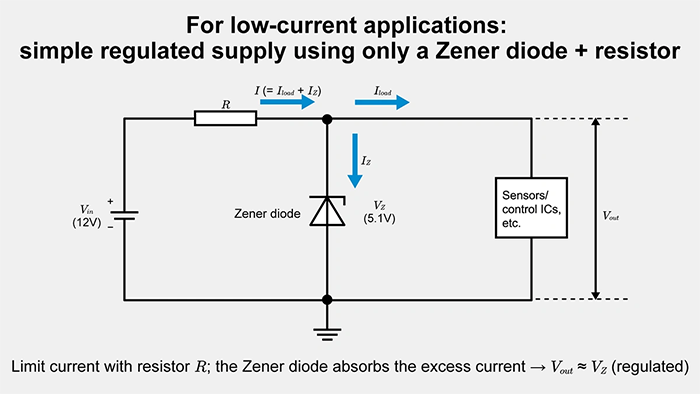
Generating a Simple Low-Power Supply
When power requirements are modest, a Zener diode can generate a stable voltage supply without resorting to a full linear regulator IC or a switching regulator. For example, you can step down from 12 V to about 5 V or 6 V by selecting a Zener diode with the desired breakdown voltage, then adding a series resistor. The diode enters the Zener breakdown region, stabilizing the voltage across it. At the same time, the resistor drops the difference between the input voltage and the stable voltage.
If you assume Vin is higher than VZ (the rated Zener voltage), then the resistor R is calculated by:
\(R = \displaystyle \frac{V_{\text{in}} – V_{\text{Z}}}{I_{\text{Z}}+I_{\text{load}}}\)
where IZ is the minimum current required to keep the diode in the Zener breakdown region, and Iload is the current required by the load.
However, this technique can be inefficient for large voltage drops and higher currents, as the resistor must dissipate the leftover power. Similarly, the diode itself must handle the power rating (voltage multiplied by current). If the current draw changes significantly, the output voltage stability can suffer. Thus, it’s ideal for low-load circuits or to provide a reference line for smaller subcircuits.
Key Selection Criteria for Zener Diodes
Although a Zener diode can simplify circuit design, you must pay attention to important parameters such as the Zener voltage, maximum current, temperature stability, and power dissipation. The following sections guide selecting the right diode and ensuring reliable performance in real-world conditions.
Operating Voltage and Power Rating
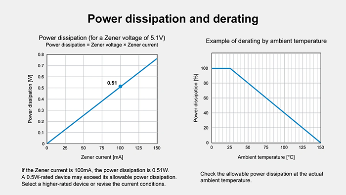
Selecting the right Zener diode starts with picking a rated Zener voltage that suits the stable voltage you need. Then you confirm that the device can handle the maximum current or power dissipation expected. Power dissipation is P=VZ×I. If you have a 5.1 V Zener diode with 100 mA flowing, that’s about 0.51 W. You’d typically want a diode rated for a higher maximum power (e.g., 1 W) to ensure longevity and safe temperature margins. If the circuit lowers its input voltage significantly while the current stays fairly constant, the resistor and diode might both dissipate substantial heat, so that must be factored into the design.
Also, consider the temperature coefficient if temperature stability is critical. Many Zener diodes drift their breakdown voltage slightly with changing ambient temperature. You might need a diode with a low temperature coefficient or design your circuit so the load can tolerate mild voltage variations.
Testing and Measurement of Zener Diodes
Testing a Zener diode ensures that its breakdown voltage, forward voltage, and overall performance align with specs. Basic checks can reveal if the diode is shorted or open. More detailed tests require applying a reverse bias voltage under controlled conditions and observing whether the diode regulates at the correct voltage across the diode terminals.
Methods for Verifying Zener Operation
A straightforward approach is to use a DC power supply with a series resistor and gradually increase the reverse bias voltage across the diode. Note the point at which the voltage across the diode stops rising significantly and measure that. This is the Zener breakdown voltage. A typical handheld meter’s diode-check function might not provide sufficient reverse voltage to detect avalanche breakdown or the onset of the Zener effect, so a specialized test with a power supply is recommended for accuracy.
Measuring Breakdown Voltage and Temperature Coefficient
Zener diodes often show changes in breakdown voltage with temperature. Lower-voltage diodes sometimes exhibit a negative temperature coefficient, while higher-voltage diodes can show a positive temperature coefficient. If your application requires a stable output voltage over a wide temperature range, you should measure the diode’s breakdown characteristics in a temperature-controlled environment.
Place the diode and a thermocouple or temperature sensor in a small thermal chamber, measure the diode voltage at a fixed test current across different temperatures, and record the resulting voltage shift. This data shows whether the chosen diode meets the voltage tolerance required for your specific climate or device enclosure.
Failure Modes and Troubleshooting
Zener diodes can fail by going open-circuit (no current flows in any direction) or short-circuit (they conduct in both directions like a wire). An open-circuit failure often means the diode no longer clamps the reverse voltage, leaving the circuit exposed to a high reverse voltage. A short-circuit failure can damage upstream components or series resistors if the circuit continues to drive large current into a nearly zero-ohm path.
Typical root causes of failure include exceeding the diode’s maximum power rating or repeated exposure to large transient surges, which degrade the pn junction over time. If you suspect the diode is damaged, measure the forward voltage with a meter, then perform a breakdown voltage check at a safe current limit. If the part no longer regulates at the specified voltage or if the measured breakdown is far from normal, it likely needs replacement. In ESD-protection scenarios, diodes should be inspected periodically, especially in devices prone to frequent discharges.
Summary
Zener diodes are crucial in many electronic circuits that require a stable voltage reference or efficient overvoltage protection. By intentionally driving the diode into Zener breakdown, designers can maintain a stable output voltage even under variable load or input voltage conditions. Whether you need to build a simple Zener voltage regulator, clamp an AC waveform’s amplitude, or protect sensitive nodes from damaging voltage spikes, these heavily doped pn junction diodes provide a versatile, cost-effective solution.
Their unique behavior under reverse bias enables them to maintain circuit integrity even when a conventional diode would break down. However, responsible design means respecting the diode’s power dissipation, maximum current, temperature stability, and breakdown region tolerances. Thorough testing, from simple meter checks to thermal testing, ensures the diode works reliably. When used correctly, Zener diodes offer a straightforward way to regulate voltage across the diode and enhance a circuit’s robustness, stability, and overall longevity.
Related article
What is a pn junction?
Diode: Structure, Operation, Types, and Applications
【Download Documents】 Basics of Si Power Devices
In this handbook, although there are so many types of power devices using Si semiconductors, the basic points are explained, focusing mainly on diodes and transistors for power supply applications. It also introduces the procedure and decision method for transistor selection when designing circuits, as well as application examples that utilize each characteristic and feature.

Diodes
Basic
-
Diode Articles
- What is a pn junction?
- What Is a Diode? How It Works, Types, and Applications
- Rectifier Diodes
- Switching Diode
- Schottky Barrier Diodes (SBD)
- Zener Diode
- TVS Diodes
- PIN Diodes
- Diode Types and Characteristics: Static and Dynamic Characteristics, Current, Voltage, and Reverse Recovery Time
- Comparing Rectifier, Switching, Schottky, and Fast Recovery Diodes
- Schottky Diode Characteristics and Thermal Runaway
- Fast Recovery Diode (FRD) Characteristics
Evaluation