Teacher Sugiken’s Motor Library|Brushless Mortor Driver
What Is a Brushless Motor Driver?
2026.02.25
In this article, we will explain motor drivers for three-phase brushless motors, covering their role, types, and specifications, along with a technical perspective. This article provides basic knowledge required for selecting motor drivers.
“What Is a Brushless Motor Driver?” is for beginners who are planning to operate a three-phase brushless motor or who would like to know what a motor driver is. This article explains the basics of motor drivers, including what kind of motor drivers are required for operating brushless motors, what types are available, and what features they have.
The information provided here should be learned before selecting and using motor drivers. We recommend reading this article for those who wish to learn basic knowledge required for understanding the features and specifications of motor drivers. For those who wish to learn the basics of motors, including the principles of motor rotation and what is done to enable the rotation, first refer to “An Introduction to Motors”, a separate article in “Teacher Sugiken’s Motor Library”, where this article is located.
Contents of “What Is a Brushless Motor Driver?”
- ・Requirements for Three-phase Brushless Motor
- ・Role of Motor Driver
- ・Configuration (Form) of Motor Drivers
- ・Controller (Conduction Waveform)
- ・Controller (Position Detection and Control Function)
- ・Power Transistor
- ・Gate Driver
- ・Applications and Features
- ・Examples of Motor Driver
- ・Conclusion
First, we will explain the requirements for three-phase brushless motors.
Requirements for Three-phase Brushless Motor
Motors are used for moving various objects in industrial applications as well as automotive equipment, home appliances, and toys. Therefore, motors generally need to satisfy requirements regarding efficiency, vibration noise, controllability/usability, reliability, and cost. The three-phase brushless motors (hereafter brushless motors or motors) covered in this article have been widely used in recent years because they can comprehensively satisfy these requirements at a high level.
We will explain these requirements below.
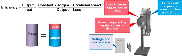
Efficiency
The efficiency here is a ratio of the motor output against the input to the motor (power). An efficient motor is a low-loss motor and is considered able to contribute to energy saving.
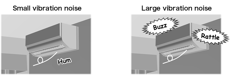
Vibration noise
A motor vibrates when the generated torque pulsates. Noise can be generated if this vibration propagates to the device on which the motor is installed. In addition, the motor itself can generate sounds. Motors with low vibration and low noise are installed on devices that are required to be quiet.
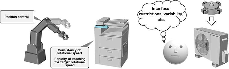
Controllability/usability
Controllability here means the ease of adjusting the rotational operation and speed of the target, responsiveness, and compliance with commands. Not only are motors required to rotate, but their rotational speed and torque must also be controllable. In addition, the simplicity of installing motors on devices, including the ease of issuing the commands for operation, automation, and deviation range, is also notable.
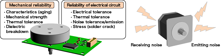
Reliability
Regarding their reliability, motors are required not to break down easily, change their characteristics, malfunction, or operate dangerously. For electrical and electromagnetic noise, the rating for noise reception as well as noise generation must be contained within the allowable range.
Cost
The cost includes the expenses for raw materials and prices of components. Reducing the number of materials and components is also an important aspect connected to environmental countermeasures.
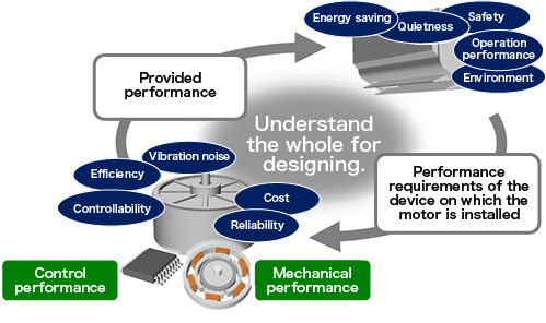
A motor is designed to satisfy the performance requirements of the device on which the motor is installed. However, achieving the highest level for every item including cost and resources is difficult and may even be considered overkill. Normally, the performance requirements are prioritized depending on the device on which the motor is installed. Therefore, designers are required to create designs with an understanding of the whole device including the installed motor.
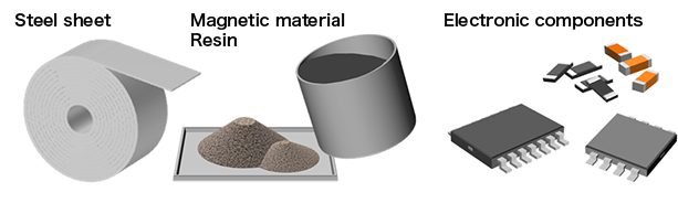
The motor performance is determined in relation to both the mechanical performance (here the motor performance determined from the materials and structures of magnets, iron plates, and other components) and the control performance (the motor performance determined from the functions and characteristics of the motor driver). One could argue that various types of motor drivers exist because they can affect the motor characteristics and change the requirements for designing the whole device.
Next, we will explain the role of motor drivers with consideration of these points.
Role of Motor Driver
A brushless motor requires an electrical circuit (motor driver) to generate a rotational magnetic field using coils (electromagnets) by applying current/voltage to the coils.
This generation of the rotational magnetic field is the most basic operation. In addition to this operation, the performances and functions shown in the figure below are required for motors.
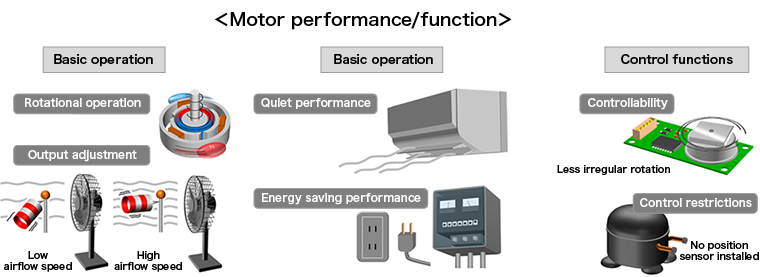
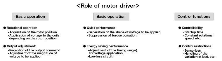
To realize these performances and functions, motor drivers play the roles shown below. Motor drivers can adjust the output voltage value freely. This feature is naturally utilized to adjust the motor output as well as for other purposes including the following: improving the quietness by suppressing the torque pulsation, control for generating torque efficiently with a reduced loss by adjusting the timing of voltage application, control of the rotational speed with a reduced rotational irregularity, and sensorless control to deal with an environment in which position sensors cannot be installed.
The roles above are examples. There are also various measures to enable these roles. Therefore, it is necessary to understand the required functions as well as the measures to enable them when selecting motor drivers.
Next, we will explain the circuit configuration of motor drivers that can perform these roles.
Configuration (Form) of Motor Drivers
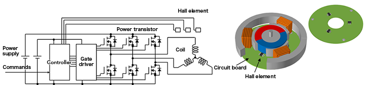
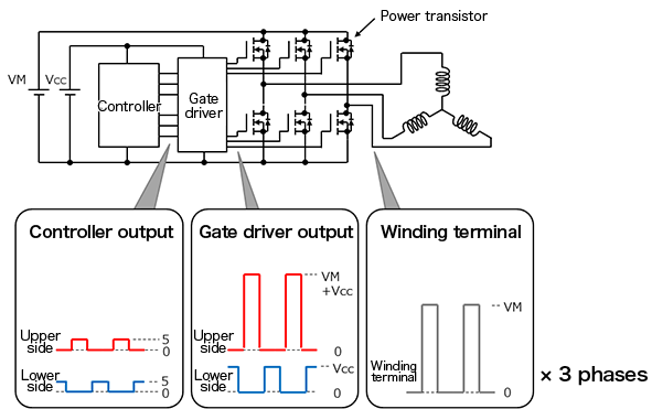
The figure below shows the basic circuit configuration of motor drivers. Motor drivers use electronic components (electronic parts) called power transistors to supply power to the motor coils, which is one of the roles of motor drivers. A power transistor refers to a transistor that can handle a relatively high power. In the figure below, a power transistor is indicated with the circuit symbol of an N-channel MOSFET. However, the symbols of a P-channel MOSFET, IGBT (N- and P-channels), and bipolar transistor (PNP and NPN) can also be used. These power transistors are connected with the power supply and serve as electrical switches. The power transistors connected with the positive side of the power supply are referred to as the upper-side or high-side transistors. The power transistors connected with the negative side (ground side) of the power supply are referred to as the lower-side or low-side transistors. The potential applied to the coils is determined by whether the upper-side or lower-side transistors are turned ON. Three-phase brushless motors use three pairs, i.e., six power transistors.
These power transistors are turned ON/OFF by a controller. Integrated circuits ( IC, referring to a component not using software here) and microcontrollers ( referring to a component using software here) are used. The controller determines the voltage to be applied to the coils based on the rotor position and external commands and it generates the ON/OFF command signals for the power transistors. (The figure below shows a circuit image when the rotor position is obtained with a Hall element. The Hall element is placed where it can detect the magnetic flux of the rotor.)
In addition to these circuits, a gate driver is used for connecting the controller and the power transistors. The main role of the gate driver is to adjust the potential and polarity of the command signals from the controller so that the potential, polarity, and current amount are sufficient for operating the power transistors.
We will explain details of these circuits later.
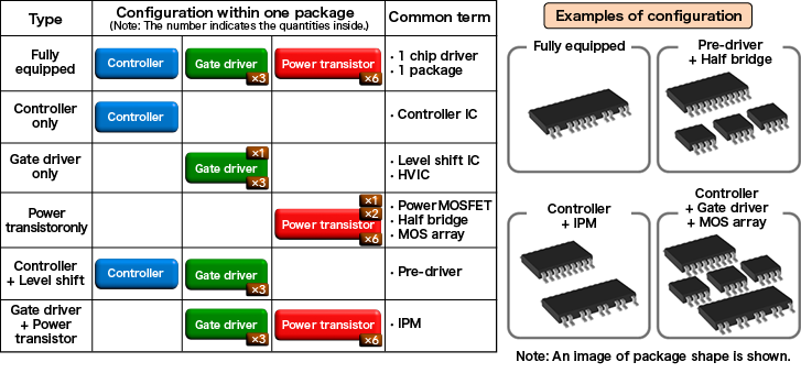
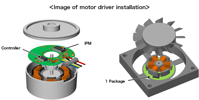
These circuit sections are configured as internal circuits with single or multiple built-in functions as shown in the table below. Therefore, a motor driver consists of one of these ICs or a combination of them.
This combination is considered in terms of its usability, freedom of design change, package size, number of wires on the board (difficulty in wiring), number of peripheral electronic components, difference in the voltage ratings of the circuit blocks, temperature rise (degree of heat dissipation), etc. Therefore, it is impossible to say which combination is the best in general. For the features of the configuration example shown in the figure, refer to “Motor Driver Configuration” in Episode 10, a separate article under “Teacher Sugiken’s Motor Driver Dojo” in “Teacher Sugiken’s Motor Library”, where this article is located.
Here, we will explain the voltages to be applied to the sections of the motor driver circuit. First, the voltage to be applied to the coils of a brushless motor is affected by the characteristics of the mechanical part of the motor. Some motors require a voltage as low as 3.3 V, while others require 340 V or higher. To apply such a voltage to the coils, the voltage rating of the power transistor must be higher than the voltage.
The voltage applied to the gate driver, which is a circuit that drives the power transistors, is the same as or higher than the voltage applied to the power transistors that are driven by the gate driver. This is because, for example, turning ON the upper-side N-channel MOSFET requires a voltage the same as or higher than the voltage to be applied to the power transistors.
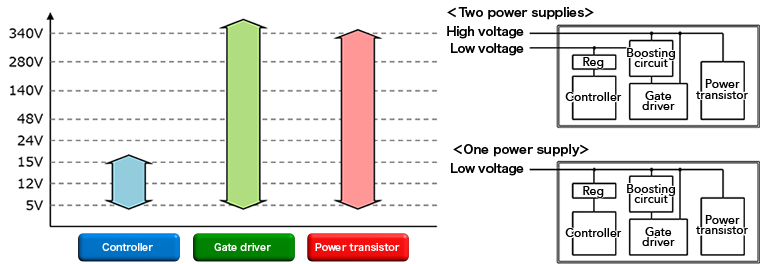
Unlike the two circuit sections above, the controllers are independent of the motor characteristics and used at a relatively low voltage.
Based on these considerations, the supply voltage may be applied to the motor driver using two systems at high and low voltages or one system at a relatively low voltage. This difference in voltages is also a factor for determining the configuration of the circuit sections (single package or combination of several components).
Note that the magnitude of the voltage to be applied to the motor coils is designed while comprehensively considering the power supply environment and power conversion efficiency of the installed devices, allowable current of the wiring, motor characteristics, reliability, and other factors.
Next, we will explain the features of the specifications of each circuit section briefly.
Controller (Conduction Waveform)
The conduction waveform is one of the specifications of motor drivers for brushless motors that is worth paying attention to. Here, the conduction waveform refers to the waveform of voltage applied to the coils. This applied voltage passes a current through the coils of a brushless motor, generating a rotational magnetic field. The conduction waveform can be considered an important specification because the operation of this rotational magnetic field affects the output torque of the motor. This conduction waveform is created by the controller generating the commands for turning ON/OFF the power transistors. Therefore, the specifications of the conduction waveform are indicated for the motor driver component on which the controller part is installed.
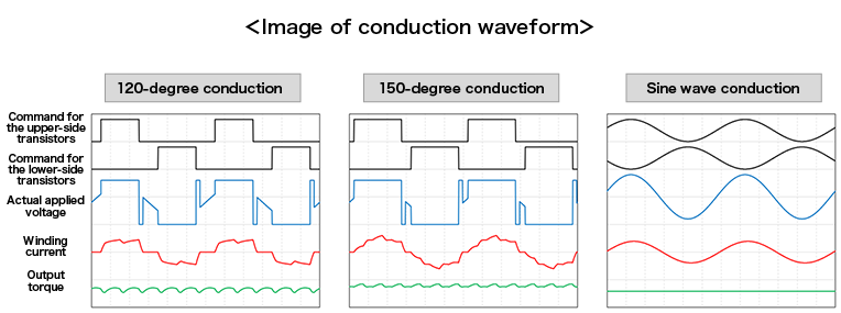
The figure below shows the basic conduction waveform of motor drivers.
In the waveform of the 120-degree conduction, the upper or lower side is turned ON in 120-degree sections and both are turned OFF in 60-degree sections (two locations) when one cycle of the conduction pattern is set to 360 degrees. It is also referred to as a 120-degree square wave. Although this conduction waveform can be generated relatively easily in terms of the control circuits, the output torque pulsates.
In the waveform of the 150-degree conduction, the upper or lower side is turned ON in 150-degree sections and both are turned OFF in 30-degree sections (two locations). It is also referred to as a broad-angle conduction. Although this conduction waveform requires a more complex control circuit, it can be generated more easily compared with the sine wave conduction described below and has an advantage in suppressing the pulsation of the output torque. In addition, the waveform can be modified from a simple square (rectangle) to further suppress the torque pulsation. Such conduction waveforms may be called by other names such as trapezoidal wave.
The waveform of sine wave conduction is sinusoidal. It is also referred to as 180-degree conduction. However, confirmation is needed because it could be confused with the 180-degree square wave (not described here). Although this conduction waveform requires a more complex control circuit, the current waveform is sinusoidal and can eliminate the torque pulsation in theory.
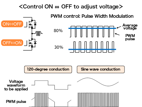
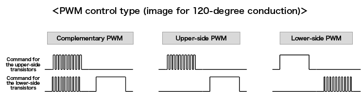
Here, we will explain the PWM control, which can be considered the basic technique for generating the conduction waveform. The PWM control utilizes pulse width modulation, which is one of the methods for adjusting the applied voltage. By adjusting the ON/OFF ratio of the upper-side and lower-side power transistors within a specified time, a voltage can be applied to the coils on average at a desired percentage relative to the supply voltage. For example, a specified time of 50 us with the upper side turned ON for 40 us and the lower side turned ON for 10 us gives an average voltage of 80%. There are several types of operation to turn ON/OFF the upper-side and lower-side power transistors. In one operation type, the upper and lower sides are complementarily turned ON according to the ratio. (One side is ON when the other side is OFF with the dead time provided.) Alternatively, only the upper side is turned ON/OFF while the lower side is OFF or vice versa.
This control method allows you to adjust the magnitude of the voltage to be applied in the 120-degree conduction. In addition, the sine wave conduction can be realized by changing the ratio sinusoidally in the 360-degree section. (This is one of the factors that makes the control circuit for the sine wave conduction more complex.)
Although the waveform is sinusoidal in the sine wave conduction described above, other waveforms are possible in the sine wave conduction.
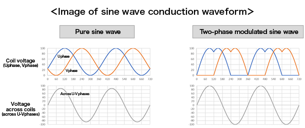
The two-phase modulated sine wave shown in the figure below is widely employed in motor driver ICs with the sine wave conduction specifications. The figure shows the waveforms of the voltage applied to the U phase and V phase coils of a brushless motor and the voltage across the U-V phases (across wires). For the two-phase modulated sine wave, although the voltage in each phase is not sinusoidal, the voltage across wires is sinusoidal. Compared with the normal sine wave (pure sine wave), it has various advantages, including that the range of power transistor switching by the PWM control is narrower (reduction in the switching loss) and the amplitude of the voltage across wires can be increased (improvement in the voltage utilization factor).
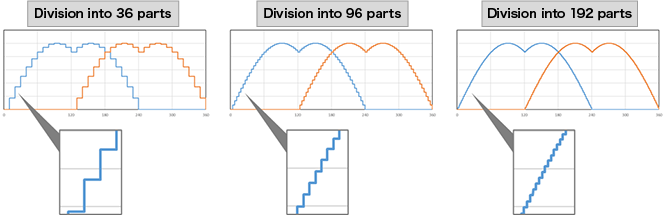
For the sine wave conduction, the number of divisions (resolution) of the waveform is also an indicator of the specifications. The number of divisions here corresponds to the number of changes in the waveform within 360 degrees (see the figure below). As the number of divisions increases, the waveform achieves a smoother sinusoidal form. However, the control circuit becomes more complex. Note that even if the number of divisions is large, the waveform cannot be generated with a performance beyond the applied voltage ratio that can be realized with each pulse of the PWM control described above.
Controller (Position Detection and Control Function)
There are various types of controllers for brushless motors depending on the methods for detecting the rotor position, command specifications, installed control functions, etc. Here, we will explain the following topics.
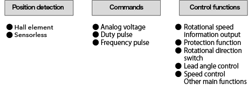
Position detection
Controllers generally generate conduction waveforms while acquiring (sensing) the rotor position. The following methods are available for detecting the rotor position: use Hall elements or detect the induced voltage. The latter is referred to as sensorless because no position detection sensor is used directly. For the acquisition of the rotor position from the induced voltage, refer to the explanation in “How Can We Know the Rotor Position from the Induced Voltage?” in “Motor Q&A”, a separate article in “Teacher Sugiken’s Motor Library”, where this article is located.
The number of signal input terminals of controllers varies with these specifications. The figure below shows an image of these terminals. A controller using Hall elements has three or six input terminals. A sensorless controller does not have any terminals to input the signal of the Hall element (it may have a terminal to input the motor coil voltage instead).
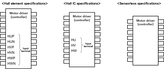
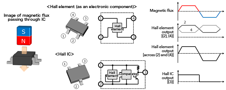
There are two types of controllers that use Hall elements because there are two types of electronic components that use the Hall element. Here, we call one type a Hall element (a name given as an electronic component) and the other a Hall IC.
A Hall element is an electronic component in which four terminals directly serve as the inputs and outputs of a Hall element as a magnetic detection element. A current flows when a voltage is applied across terminals (1) and (3) in the figure below. Then, depending on the magnetic flux passing through the IC, a voltage appears on terminals (2) and (4) as shown in the figure. The controllers with the Hall element specifications generally use the difference in voltages on these two terminals as the result of magnetic flux detection. Therefore, controllers with these specifications have two (P and N) input terminals for each U, V, and W phase (see the figure above).
The Hall IC is an electronic component that uses the internal circuit of the IC to process the signal of the output voltage of a Hall element as a magnetic detection element and outputs the two potentials: High and Low. Since there is one output signal, the controllers with the Hall IC specifications have three signal input terminals. (The names such as Hall element and Hall IC are examples. The terminal names may also include numbers and +/-, for example, H1+, H1-, H1, and H2.)
The controllers with the specifications that use the Hall element (electronic component) may support the use of the Hall IC. In such cases, input the reference-voltage to either of the input terminals, whichever is unused (for example, when the Hall IC signal with 5 V for the High voltage and 0 V for the Low voltage is input to HUP, input 2.5 V to HUN). However, confirmation is needed because the input voltage range is specified for the controller terminals.
Note that some controllers may use only one or two Hall elements.
Sensorless controllers acquire the rotor position by detecting the phase of the induced voltage (although other sensorless methods are available, we will explain the induced voltage detection here). The induced voltage can be detected as the voltage of the coil terminals while the motor is rotating and when no current flows through the target coils. Therefore, if the coil terminals have been connected with the motor driver since the beginning, other signal input terminals are not required.
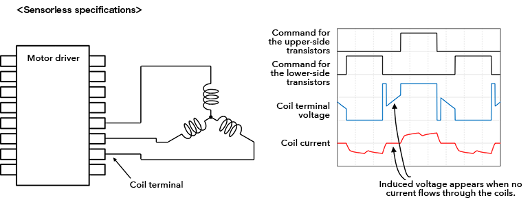
For the sensorless controllers using the induced voltage detection method, it is necessary to check the specifications regarding the following two points: the response when the motor is not rotating (when no induced voltage is generated) and the response to the requirement that the coil current must be reduced to zero in order to detect the induced voltage. In particular, the method of starting the motor rotation in the former and the conduction waveform during the sine wave conduction in the latter vary depending on the controllers. Select the most suitable controller based on your purpose.
A conduction method known as full sine wave may be indicated for the controllers using the sine wave conduction. This shows that the conduction waveform is sinusoidal without disruption, in contrast to the sensorless motor drivers (controllers), which disrupt the sinusoidal waveform during the induced voltage detection.
Commands
The command signals received by controllers include the commands for the adjustment values, including the magnitude of the output voltage and the rotational speed. These command signals have three main specifications as follows: the analog voltage, the pulse signal using the High/Low ratio (duty) of the pulse for directions, and the pulse signal using the frequency (cycle) for directions. We will explain each signal below.
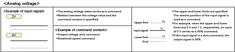
・Analog voltage command
The controller receives a voltage value as a command. The upper and lower limits of the command voltage values are specified. The command information is determined by relative comparison between the specified values and the command voltage value. For example, when the upper limit is 5 V and the lower limit is 1 V, a command with 1 V or lower is assigned a value of 0 (zero) and a command with 5 V or higher is assigned a value of 100 (%), and the values are specified between these limits. In this case, an input with 3 V is considered 50 (%) and an input with 4 V is considered 75 (%), and so on.
If this is a command for the magnitude of the output voltage, the driving circuit usually outputs 50% voltage for the 3 V input and 75% voltage for the 4 V input. If this is a command for the rotational speed, check the characteristics data (for example, on a graph) showing the relation between the command values and the rotational speed provided in the data sheet (specifications) of the controller.
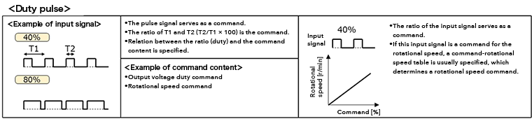
・Duty pulse command
The duty pulses are received as commands. Here, the duty pulses are pulse signals at a constant frequency with varying percentages for High (varying ratios between High and Low) as shown in the figure below. These ratios serve as commands. It is necessary to check the data sheet (specifications) of the controller to be used for the voltage level (threshold) to distinguish the High and Low signals and the range of frequency at which the signals can be input.
If this is a command for the magnitude of the output voltage, the command ratio is usually reflected directly to the magnitude. If this is a command for the rotational speed, check the characteristics data (such as a graph) showing the relation between the command values and the rotational speed provided in the data sheet (specifications) of the controller.
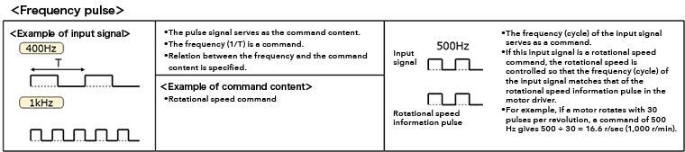
・Frequency pulse command
The frequency pulses are received as commands. Here, the frequency pulses are pulse signals with varying frequencies as shown in the figure below. These frequencies serve as commands. These frequencies may be converted to commands from zero to 100 and then used as commands for the magnitude of the output voltage and the rotational speed. However, these frequency pulse commands are usually compared directly to the rotational speed information pulses for the motor control. Specifically, this method compares the motor rotational speed information signal (with varying frequencies depending on the motor rotational speed generated from the signals from the Hall element, etc.) generated by the controller with the frequency (cycle) of the command signal and then it controls the motor rotational speed so that it matches the frequency of the command signal. It is necessary to check the data sheet (specifications) of the controller and the specifications (the number of poles, etc.) of the motor in order to understand the relation between the frequencies of the command signals and the actual rotational speed of the motor.
In addition to these, the data communications may be used as commands.
Control functions
In this section, we will briefly explain some of various controls and functions installed on the controllers.
・Rotational speed information output
Some devices on which motors are installed use the motor rotational speed information to control the motors. For such a device, the controller outputs a signal referred to as a frequency generator (FG) as the rotational speed information.
The FG signal changes its frequency (cycle) depending on the motor rotational speed. Many controllers output a signal (example 1) using one of the Hall element signals (see the figure below) or a signal (example 2) combining the three Hall element signals. Some controllers allow you to select which signal to output. For the FG signals generated in this way, the number of pulses per motor revolution depends on the number of poles of the motor. For four-pole motors, the number of pulses per revolution is two or six. For eight-pole motors, the number of pulses per revolution is four or 12.

If the device on which the motor is installed can support only the specified numbers of pulses per motor revolution, the frequency of the FG signal needs to be modified when the number of poles of the motor is incompatible with the specified numbers of pulses. Some controllers are equipped with a frequency conversion function for such signals.
・Protection function
The controllers have a function to protect the motor driver and the motor. The table below shows examples of the protection function. The function detects a state to be protected or error and performs operations such as turning OFF the power transistors. Since the items may be called by different names, it is necessary to understand the content, rather than judging only by the names.
| Item | Content | Main operation |
|---|---|---|
| Current limit (reduction) | Limits (reduces) the current flowing through the transistors and coils. | Adjusts the output voltage |
| Overcurrent | Limits the maximum current flowing through the transistors and coils. | Turns OFF the power transistors. Returns with the time or PWM cycle. |
| Overheat | Limits the temperature of the electronic components. | Turns OFF the power transistors. Returns with reset of some operations of the controller and decrease in the temperature. |
| Low voltage | Monitors whether the voltage decreases below the operating voltage of the circuit. | Turns OFF the operations of the controller and the gate driver. Returns with the increase in the voltage. |
| Overvoltage | Monitors whether the voltage increases above the operating voltage range of the circuit. | Turns OFF the power transistors. Returns with decrease in the voltage. |
| Arrest (lock) | Monitors whether the motor is rotating. | Turns OFF the power transistors. |
| High speed | Monitors whether the rotational speed of the motor exceeds a specified value. | Turns OFF the power transistors. Returns with decrease in the rotational speed. |
| Hall error | Monitors whether the Hall signal is erroneous. | Turns OFF the power transistors. |
| External input | Accepts external operation stop signals (from other circuits). | Turns OFF the operations of the controller. Turns OFF the power transistors. |
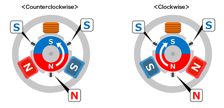
・Rotational direction switch
This function switches the directions of motor rotation while fixing (not changing) the layout of the Hall elements for the rotor position detection. Even if the Hall element information (N and S poles) to be input to the controller is the same, switching the rotational direction setting changes the magnetic poles of the electromagnets generated in the coils, generating a motor torque in the opposite direction. Although this example is for the operation with the Hall element specifications, this function is also available for the sensorless controllers. Note that the actual direction of the motor rotation (clockwise or counterclockwise) is determined by how the coils and the motor driver are connected and where the Hall elements are placed.
・Lead angle control
Brushless motors can achieve the maximum torque by continuously generating the rotational magnetic field (with the electromagnets) at an appropriate angle against the rotor position. If this angle is deviated, the same strength of the electromagnets may generate a smaller torque. This means a decrease in the output power against the input power, resulting in a decrease in the efficiency. Therefore, the controller acquires the rotor position and adjusts the timing for applying the voltage to the coils.
However, when the motor is actually operated, a delay in current occurs due to the armature reaction and the coil inductance. The lead angle control is a function to correct this effect. Since the phase is advanced from the initial conduction timing, it is referred to as the “lead angle” (advancing the angle).
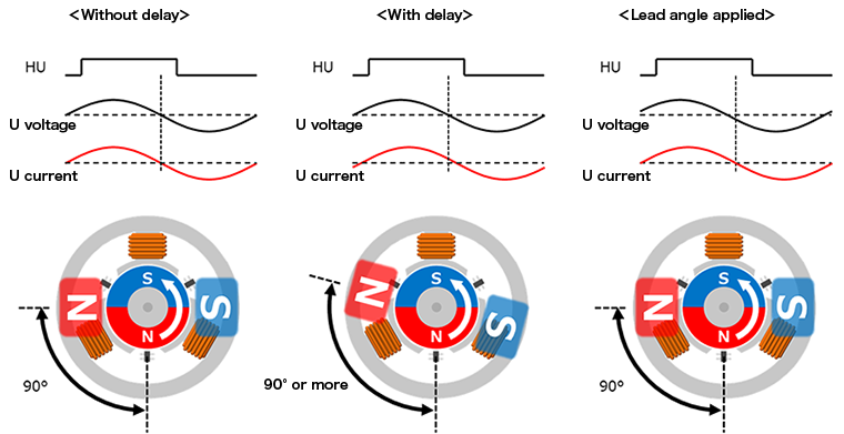
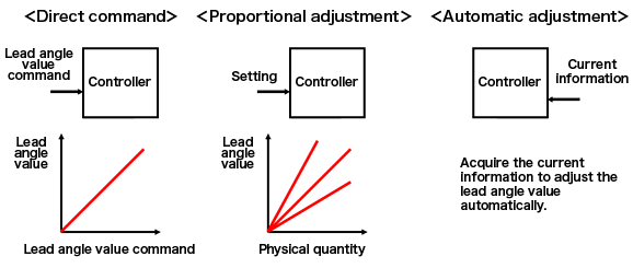
Since this delay in current due to the armature reaction and the inductance varies depending on the magnitude of the magnetic force of the electromagnets and the motor rotational speed, it is necessary to adjust how much the conduction timing is advanced accordingly. There are several methods for making this adjustment. In one method, the controller receives an external command for the lead angle value (direct command). Alternatively, the controller can determine the lead angle value based on the rotational speed, voltage command, and physical quantities such as the magnitude of the current (proportional adjustment). Since the most appropriate lead angle value for the physical quantities varies depending on the motors, some controllers can specify the proportionality constants. In addition to the simple linear proportion, the proportionality constant may be changed after a specified value or the secondary proportion may be used. Some controllers can automatically adjust the lead angle without such steps (automatic adjustment). This method requires the current phase detection.
・Speed control
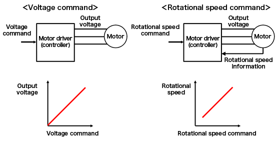
Up until now, we have explained that the motor drivers (controllers) mainly receive the command for the output voltage and then apply a specified voltage to the motor coils. In addition, we have indicated that the devices on which the motors are installed can adjust the rotational speed by outputting the FG signals (rotational speed information signals). However, some controllers of motor drivers are equipped with a built-in adjustment function for this rotational speed.
Such controllers receive a rotational speed command, compare it with the rotational speed information of the motor, and then automatically adjust the output voltage. Care must be taken because the rotational speed of the command may have upper and/or lower limits.
・Standby
The controllers keep operating the circuit even when the motor is not operated so that the control operation can be started once a command is received. At this time, a current flows through the circuit, consuming power. To reduce this power consumption during the standby, some controllers are equipped with a function to stop some circuit operations. This function is referred to as a standby function, standby power reduction mode, power saving function, etc.
・Soft start
When the motor driver operation and the motor are stopped and a high voltage command (such as a command for 100% output voltage) is received, application of a high voltage to the coils causes a current to flow suddenly. If this increase in current generates a large torque, noise or significant vibration may occur. The soft start prevents such behaviors. The soft start function prevents a sudden increase in current when the motor rotation is started and increases the current gradually.
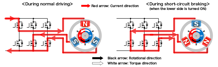
・Short-circuit brake
The short-circuit brake short-circuits (electrically connects) the coils during the motor rotation and passes the current that generates a negative torque. This function short-circuits the coils by turning ON all the power transistors on the upper or lower side. The short-circuit brake can generally stop the motor rotation faster than turning OFF all power transistors to stop the motor driving.
The figure below shows the direction of the current flowing through the coils, the orientation of the electromagnets, and the direction of the generated torque at the moment when the rotor is located at the position shown in the figure. When all the power transistors on the lower side are turned ON, the current flows in the opposite direction to the normal driving and the pole of the electromagnets is opposite as well. As a result, a negative torque is generated (in the direction of stopping the rotor rotation).
We have explained the specifications and functions related to the controllers so far. The actual controllers are equipped with some of these specifications and functions. To operate a motor, select a controller suitable for your purpose from those controllers.
Power Transistor
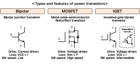
In motors, power transistors are used to apply voltage and pass current through the coils. Therefore, the voltage to be applied, current to be passed, loss when a current is passed, and speed of ON/OFF switching (SW speed) become indicators.
The figure below shows the types and features of the power transistors mainly used for motors. Bipolar transistors (bipolar junction transistors) are current driven transistors that are turned ON by passing a current through the base. The loss in the ON state is the power that is the product of VCE (collector-emitter voltage) multiplied by the collector current and the power of the base current. Although these are basic transistors with a long history, they are not suitable for the PWM control because the switching cannot be performed at a high speed. As a result, they are used less often in such motor applications recently. MOSFETs are voltage driven transistors that are turned ON by applying a voltage to the gate. The product of the on-resistance (RON) multiplied by the square of the drain current is the power consumed as a loss. They have some advantages, including that it is unnecessary to keep passing the current through the gate and the switching is fast. However, when the drain current becomes larger, the loss increases by the square of the drain current, posing a problem. IGBTs are transistors with the advantages of both bipolar transistors and MOSFETs. Since they are voltage driven, consumption of the gate current is relatively small and the loss remains proportional to the first order of the current. However, the switching speed is intermediate.
Recently, MOSFETs and IGBTs are often used mainly for small and large currents, respectively, using the magnitude relationship between RON × current and VCE as the threshold.
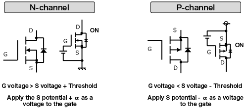
Next, we will explain the configuration of power transistors in motors using MOSFETs as an example. There are two specifications for MOSFETs: N-channel (N-type) and P-channel (P-type). The difference in principle between these two is whether a current is passed with electrons or holes. According to this difference, an N-channel MOSFET is turned ON when a voltage higher than the threshold is applied across the source (S) and gate (G) terminals, while a P-channel MOSFET is turned ON when a voltage lower than the threshold is applied across the source and gate terminals. Note that the N-type can generally be downsized further compared with the P-type when both types are given characteristics that allow them to pass the same magnitude of current. This is also affected by whether electrons or holes are used.
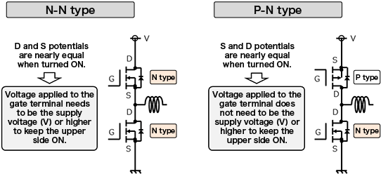
The motor drivers for brushless motors use the N-type for the lower-side MOSFET. This is because the source potential of the lower-side MOSFET is the ground, making it easier to generate the gate command voltage and the N-type is smaller compared with the P-type as described above. The N-type and P-type may be used for the upper-side MOSFET. Either can be used because of the following reasons. If the N-type is used, although the characteristics can be matched with the lower-side MOSFET (and downsizing is possible), the voltage needs to be higher than the power supply (V) connected with the power transistors to keep the upper side ON. If the P-type is used, although the voltage does not need to be higher than the power supply (V), the size increases (or the characteristics are changed) compared with the N-type. The voltage of the power supply connected with the power transistors is usually the highest as a voltage externally supplied to the motor driver circuit. Therefore, one of the important choices is whether or not a voltage higher than the supply voltage is required.
Note that the voltage and current to be applied to the motor coils vary depending on the device on which the motor is installed as well as the motor characteristics. It is necessary to select power transistors that can handle the voltage and current required in the motor.
Gate Driver
Gate drivers are electronic components that transfer the command signals from the controller to the power transistors.
The figure below shows an example of the signals when N-channel MOSFETs are used on both the upper and lower sides. The controller outputs the command signals with Low at 0 V and High at 5 V. These signals cannot turn ON/OFF the upper and lower MOSFETs directly. As described above, it is necessary to apply a voltage higher than the threshold to the source of a N-channel MOSFET and the source voltage of the upper-side MOSFET can be the supply voltage (VM in the figure below). As shown in the figure, the gate driver adjusts the amplitude of the lower-side command signals to VCC. This VCC is set to a value higher than the threshold of the MOSFET. In addition, the voltage that turns ON the upper-side MOSFET is set to VM + VCC. Compared with the output capacity of the controllers, the output capacity of the gate drivers is generally increased so that it can supply and absorb a larger amount of current. This is because a certain amount of current is required to turn ON/OFF MOSFET (the switching speed of MOSFET may be limited if this amount of current is insufficient).
Based on the above, the roles of the gate drivers are the adjustment of the amplitude of the command signals, adjustment of the potential depending on the supply voltage (VM), and increase in the maximum value of the amount of current. In addition, the gate drivers also change the polarities when a P-channel MOSFET is used on the upper side.
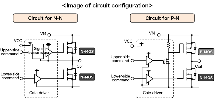
The figure below shows an image of configuration of the circuit that performs the operation above. For the N-channel-N-channel type (N-N), the lower-side command signals are output through a buffer circuit (here, the buffer circuit adjusts the signal magnitude (amplitude) and the current supply capacity). On the upper side, the signal level of the command signals is adjusted through the signal transmission circuit and the signals are output through the buffer circuit. The voltage used here may be higher than VM.
The lower side of the P-channel-N-channel type (P-N) is the same as the N-N type. The upper side is configured as shown in the figure, for example. The ON command turns ON the transistor beyond the buffer circuit. This operation decreases the gate voltage of the upper-side MOSFET and turns it ON. As described above, the circuit configuration of the gate driver depends on whether the power transistors are the N-N or P-N type.
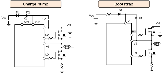
For the N-N circuit, a voltage higher than VM (the power supply on the upper side of the power transistors) is required. This voltage is usually generated with a boosting circuit inside the motor driver. There are two main types of boosting circuit as follows.
One is a circuit referred to as a charge pump. This circuit is operated so that the voltage of the VCP1 terminal is set to 0 and VM alternately in order to charge a voltage in capacitor C2. This operation sets the VCP terminal voltage to VM + VCC (excluding the voltage drop in the diodes), which can be used as the boosting voltage.
The other is a bootstrap circuit. A voltage is charged to capacitor C1 when the lower-side power transistor is turned ON and the voltage of the VS terminal falls to nearly zero (the ground potential). This operation maintains the potential difference of VCC between the VB terminal and VS, which can be used as the boosting voltage.
For the operations and features of these two circuits, refer to “Boosting circuits” in “Knowledge of Electrical Circuits” in Episode 12, a separate article under “Teacher Sugiken’s Motor Driver Dojo” in “Teacher Sugiken’s Motor Library”, where this article is located.
Applications and Features
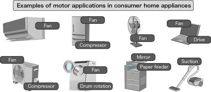
Brushless motors are installed on devices and used in various applications. For example, the motors are used in blast fans, compressors, washing machine tubs, polygonal mirrors and paper feeders of copy machines, drives of personal computers (hard discs and optical drives), and suction devices of vacuum cleaners, to name just a few examples related to consumer home appliances.
Operating these devices is accompanied by features and requirements (restrictions or unrequired matters) unique to each device. For example, fans are required to rotate at a constant speed, while there is no strict requirement regarding irregular rotation or precision of the rotational speed. Such requirements regarding irregular rotation and precision of the rotational speed are set for the motors that rotate devices directly related to the equipment performance, such as polygonal mirrors, paper feeders, and drives. Compressors require sensorless controllers and vacuum cleaners require a high rotational speed.
If you attempt to use a single motor driver to handle motors with various features and requirements (restrictions), the performance may be considered overkill or conflicting functions may be installed. Accordingly, some motor drivers offer performance suitable for the respective features, for example, for fans or polygonal mirrors.
In addition, the voltage of the power supply to be input to the motor (power supply connected with the power transistors) may mainly be a voltage used by commercial power supplies (100 V AC and 200 V AC) that is rectified to DC or decreased to a lower voltage. The former is 140 V DC or 280 V DC and may be called a high voltage, while the latter is 24 V DC, 12 V DC, or 5 V DC and may be called a low voltage. The motor drivers may be called by names that specify the rated voltage band, such as high voltage drivers or low voltage drivers, to indicate the supported voltage range.
Examples of Motor Driver
In this section, we will introduce the specifications, features, and main applications of several motor driver IC provided on ROHM’s product information page.
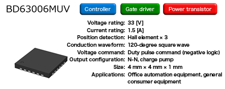
・Three Hall elements, low voltage, and 120-degree square wave
BD63006MUV is a fully equipped motor driver IC with a recommended voltage from 8 to 24 V and it can apply a current of 1.5 A. Three Hall elements are used for the rotor position detection. The conduction waveform is a 120-degree square wave. The output voltage can be adjusted by applying the duty pulse command. The built-in power transistors are the N-N type. A charge pump is used to generate a voltage.
A power saving circuit, rotational direction switch, short-circuit brake function, and various protection functions are also installed. Main applications are in motors installed on office automation equipment and general consumer equipment.
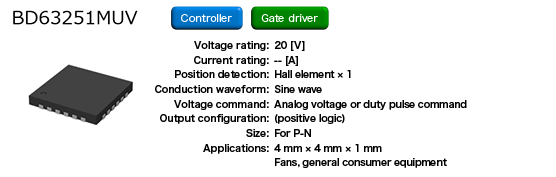
One Hall element, low voltage, and sine wave
BD63251MUV is a pre-driver IC (controller and gate driver) with a recommended voltage from 5.5 to 15 V and it is used in combination with power transistors with the P-N configuration. One Hall element is used for the rotor position detection. The conduction waveform is a sine wave. The output voltage command (signal to the power transistors) can be adjusted by selecting and applying either the analog voltage command or the duty pulse command. Since this product is for the P-N type, it has no boosting circuit.
The automatic lead angle control, fixed lead angle adjustment, soft start function, rotational direction switch, and various protection functions are also installed. Main applications are motors for fans installed on servers and personal computers.
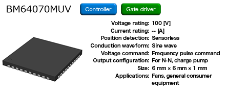
Sensorless, intermediate voltage, and sine wave
BD64070MUV is a pre-driver IC with a recommended voltage from 28 to 77 V and it is used in combination with power transistors with the N-N configuration. The rotor position is detected with the zero-cross point of the induced voltage (at which the voltage polarity changes). The conduction waveform is a sine wave (the sinusoidal waveform contains some sections where the conduction is turned OFF for detecting the induced voltage). This product has a built-in speed control (feedback) circuit and the rotational speed can be adjusted to a desired value by applying the frequency pulse command. Since this product is for the N-N type, a charge pump is used to generate a voltage.
The dead time setting function, power saving function, rotational direction switch, short-circuit brake function, and various protection functions are also installed. Main applications are motors for fans and motors installed on general consumer equipment.
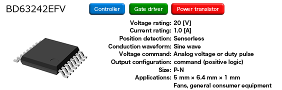
Sensorless, low voltage, and sine wave
BD63242EFV is a fully equipped motor driver IC with a recommended voltage from 5 to 16 V and it can apply a current of 1.0 A. The rotor position is detected with the zero-cross point of the induced voltage (at which the voltage polarity changes). The conduction waveform is a sine wave (the sinusoidal waveform contains some sections where the conduction is turned OFF for detecting the induced voltage). The output voltage can be adjusted by selecting and applying either the analog voltage command or the duty pulse command. The built-in power transistors are the P-N type and no boosting circuit is installed.
The rotational direction switch and various protection functions are also installed. Main applications are motors for fans inside refrigerators and motors installed on general consumer equipment.
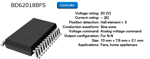
Three Hall elements and sine wave
BD62018BFS is a controller IC with a recommended voltage from 10 to 18 V and it is used in combination with a gate driver supporting the N-N type and power transistors. The recommended voltage is the supply voltage of the controller IC and does not limit the voltages of the gate driver or the power transistors. Three Hall elements are used for the rotor position detection. The conduction waveform is a sine wave. The output voltage can be adjusted with the analog voltage command. The controller IC outputs the command signals with a polarity based on the N-N configuration for turning ON/OFF the power transistors.
The lead angle adjustment function, rotational direction switch, and various protection functions are also installed. Main applications are motors for fans, motors for pumps, and motors installed on home appliances.
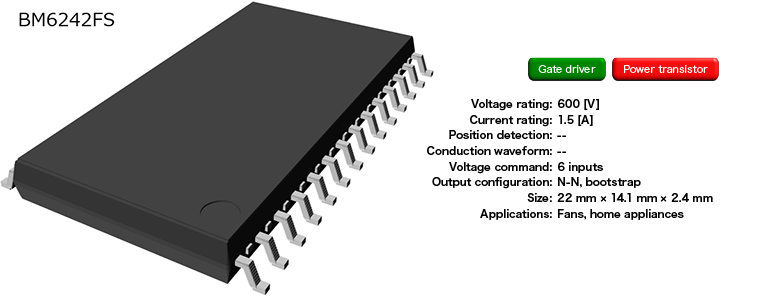
High-voltage gate driver and power transistor (IPM)
BM6242FS is an intelligent power module (IPM) with a recommended voltage of 400 V or lower. It can pass a current of 1.5 A and is used in combination with a controller IC. The built-in power transistors are the N-N type. A bootstrap is used to generate a voltage.
Various protection functions and the signal output function to indicate the protection operation in progress are also installed. Main applications are motors for fans, motors for pumps, and motors installed on home appliances.
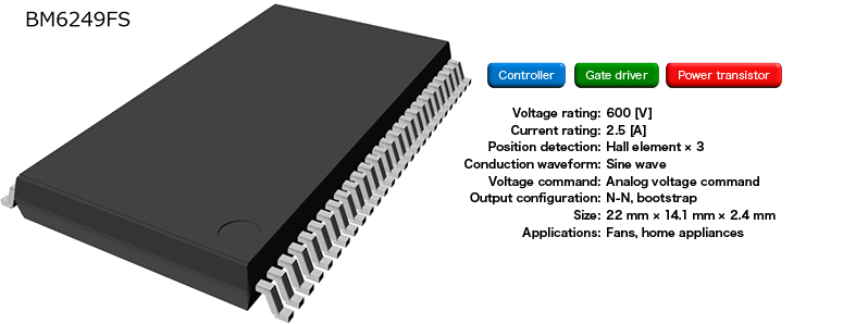
Three Hall elements, high voltage, and sine wave
BM6249FS is a fully equipped motor driver IC with a recommended voltage of 400 V or lower and it can apply a current of 2.5 A. Three Hall elements are used for the rotor position detection. The conduction waveform is a sine wave. The output voltage can be adjusted with the analog voltage command. The built-in power transistors are the N-N type. A bootstrap is used to generate a voltage.
The lead angle adjustment function, rotational direction switch, various protection functions, and signal output function to indicate the protection operation in progress are also installed. Main applications are motors for fans, motors for pumps, and motors installed on home appliances.
Conclusion
The above concludes my explanation for “What Is a Brushless Motor Driver?”
Brushless motor drivers have not only various types of general specifications, such as rated voltage and current, but also various types of methods for detecting the rotor position, conduction waveforms, and control functions. When selecting motor drivers, it is necessary to find the types suitable for your purpose and application. Therefore, it is important to have knowledge of the motor and devices to be installed as well as knowledge of the motor drivers.
We hope the content of this article, “What Is a Brushless Motor Driver?”, will help readers to select the optimal motor drivers in the future.
Teacher Sugiken’s Motor Library
Teacher Sugiken’s Motor Driver Dojo
- [Episode 1] I Can See Them! Motor Fairies
- [Episode 2] Sugiken appears! The first step to becoming a super engineer
- [Episode 3] All of Sudden, a Rival Appears for Ichinose Manabu!?
- [Episode 4] A Sudden Closeness?! New Things the Two Have in Common
- [Episode 5] Passion! Which Thoughts Did Ichinose Sense from Ninomiya?
- [Episode 6] Test showdown! A serious battle between Ichinose and Ninomiya!
- [Episode 7] This Is Just the Beginning! Ichinose and Friends’ Motor Driver Dojo
- [Episode 8] The First Meeting! Lessons Learned in a Real Setting
- [Episode 9] A Shortcut to Becoming a Super Engineer!? Learning from the User’s Perspective
- [Episode 10] Beyond the Questions! What Engineer Ichinose Learns
- [Episode 11] Learning And Growing: It’s Not Just About Turning the Motor!
- [Episode 12] To the Next Stage! The Door To Becoming a Super Engineer Opens
An Introduction to Motors
Brushless Mortor Driver
Motor Q&A