Teacher Sugiken’s Motor Library|Motor Q&A
How Can We Know the Rotor Position from the Induced Voltage?
2025.04.23
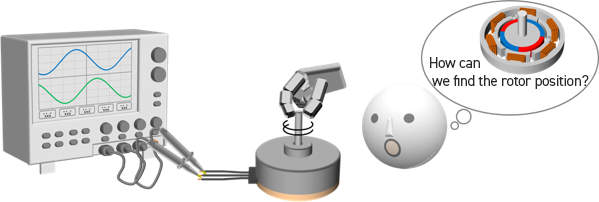
The question we ask this time is how it is possible to learn the rotor position from the induced voltage. More precisely, how is it that we can infer the position of the rotor by observing the induced voltage that appears in the windings of a brushless motor? The relationship between the induced voltage and the rotor position is important for understanding brushless motor driving, and so is explained in detail below.
●Statement of the question
The induced voltage is the voltage that appears across the winding ends when for example a brushless motor is rotated by turning the shaft by hand. How is it possible to determine the rotor position just by detecting this induced voltage?
Among motor drivers for use with brushless motors, there are drivers equipped with sensorless control that are able to run the motor without using a Hall element or other position sensor. Sensorless control can employ various methods, but methods in which the waveform of the induced voltage and in particular the zero-cross point is detected to infer the rotor position, used in the motors that are the subject of the question addressed here, are widely employed.
What is the relationship between the induced voltage and the rotor position? We begin by considering the principle of occurrence of an induced voltage, which will offer a clue.
Induced Voltage in a Brushless Motor
An induced voltage is the potential difference that appears across the ends of windings (a coil) due to the phenomenon called electromagnetic induction. Here, electromagnetic induction is the phenomenon in which, when the amount of magnetic flux passing through a coil has changed, a voltage appears in the coil in the direction causing a magnetic field that opposes the change (tries to maintain the original magnetic flux amount). If for example a magnet (N pole) is brought close to a coil as in the center image below, the rightward magnetic flux inside the coil increases. Then, the coil tries to generate a leftward magnetic field so as to suppress this increase. The direction of the current in the coil that creates the leftward magnetic field is as shown in the image, in accordance with the right-hand rule, and a voltage with the corresponding polarity appears across the ends of the coil. Conversely, if the magnet is moved away, the magnetic flux decreases, and so a current and voltage appear in directions that cause the magnetic flux to increase (see the figure on the right).
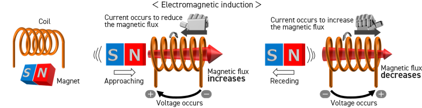
The magnitude of this voltage that appears across the coil ends is proportional to the size of the change in magnetic flux. Hence the induced voltage (Vbemf) is expressed as the derivative of the magnetic flux amount (equation below). The equation indicates that the magnitude of the induced voltage is proportional to the number of coil windings n. If the N pole is taken to be positive and the left-side end of the coil in the figure is used as reference for the voltage, then the magnetic flux Φ is signed negative in the equation.

Inserting this induced voltage phenomenon into the motor operation, we have what is illustrated below. The figure shows how the magnetic flux passing through the stator changes when the permanent magnet rotor has rotated within the stator.
The path through which magnetic flux leaves the N pole of the permanent magnet and enters the S pole is shown in orange. At the position shown in figure (1), the coil A teeth (the magnetic part around which the conductor is wound) are facing the S pole, and magnetic flux facing the S pole passes through. When the rotor rotates counterclockwise from this position, at the position in figure (2) a part of the tip of the coil A teeth begins to oppose the N pole, and the area in opposition to the S pole decreases, so that the magnetic flux passing through coil A is reduced. As the rotor further rotates, at position (3) the magnetic flux passing through coil A becomes zero (upon further rotation the amount of magnetic flux increases).
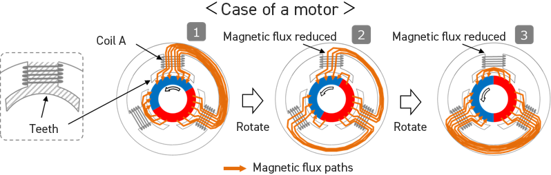
As seen in the figure, in the case of a motor, through the approach and retreat of the permanent magnet, the rotor rotates, and the polarity and flux density of the magnet opposing the coil (teeth) change, so that an induced voltage occurs.
The above concludes our explanation of the occurrence of an induced voltage in a brushless motor.
Rotor Position and Induced Voltage Waveform
Let us consider the relationship between the rotor position and the induced voltage waveform, drawing on the principle of induced voltage occurrence described above. Before this, however, we explain the meaning of the rotor position.
What Reference is Used for the Rotor Position?
In order to know a rotor position, a reference is needed to specify that position. For example, references used in specifying positions on the earth (latitudes and longitudes) include the North Pole and astronomical observatories; and references for a point 100 meters ahead might be a sign or a person stating this distance. What, then, would be a reference for a rotor position? In order to understand this, it is first necessary to understand the reason for determining the rotor position.
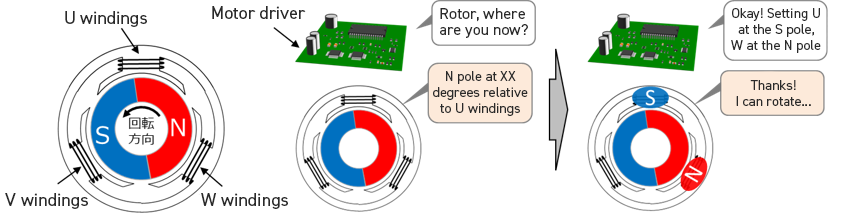
Why is it necessary to determine the rotor position when driving a brushless motor? Put simply, this information must be used to decide where to create the windings magnetic field. In a brushless motor, the attractive/repulsive force between the rotor permanent magnet and the windings magnetic field is used to rotate the rotor; in order to obtain this force, it is important that the windings magnetic field be created at an appropriate position with respect to the permanent magnet. Hence we use the windings as the reference for specifying the rotor position. More precisely, the relative position (angle) between the rotor permanent magnet and the stator windings is used to specify the rotor position.
For example, by identifying the rotor position as “the position in which the N pole is at XX degrees with respect to the U windings”, as in the figure below, it is possible to determine at what position to create the windings magnetic field so as to rotate the rotor in the desired direction.
Here, the position of the N pole means the position of the center of the N pole part. The rotor position may be expressed with reference to the position of the pole center, as in this case, or with reference to the pole transition point (transition between poles). In the latter case, the position would be expressed as “the position of the transition from the S pole to the N pole is XX degrees from the U windings”. Here, “the U windings” means the position of the center of the teeth around which the U phase windings are wound.
Relationship Between Rotor Position and Induced Voltage Waveform
Now that we know that the rotor position is determined with the windings as reference, we will now consider the relationship between the rotor position and the induced voltage waveform.
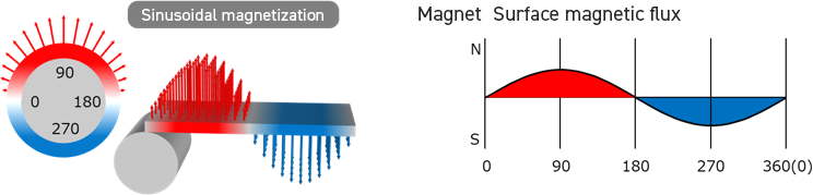
In order to think about the induced voltage waveform, we must first determine the magnetic flux quantity (Φ). To do so, we shall assume that the rotor magnetization waveform (the magnetic flux distribution of the permanent magnet) has a shape like that shown below. This waveform is generally what is called a sinusoidal magnetization waveform; the rotor is magnetized such that the magnetic flux density is distributed sinusoidally.
The figures below show the changes in the magnetic flux quantity passing through the windings (teeth) and the induced voltage when the rotor has rotated through one rotation relative to the windings. Once again, the windings (here the stator) serve as reference when specifying the rotor position. In order to aid understanding of the amount of magnetic flux passing through the teeth, the magnetic flux when the rotor moves to positions (1) through (5) is also shown.

When the rotor is at the position shown in (1) above, the windings oppose both the N and S poles of the magnet, so that almost no magnetic flux passes through the teeth. Hence the magnetic flux at the teeth is zero. When the rotor rotates counterclockwise toward rotor position (2), the N pole area of the magnet that opposes the teeth increases. The magnetization waveform in the magnet is assumed to be sinusoidal, so that at this time the teeth magnetic flux increases sinusoidally. At position (2), the teeth magnetic flux is maximum, and at position (3) it again returns to zero. Upon further rotating counterclockwise to position (4), the magnetic flux (now directed toward the S pole) reaches maximum, and at position (5) it is again zero (the rotor has returned to position (1)).
Through this rotor movement, the induced voltage occurs as shown in the figures (the induced voltage is the amount of change (differential) of the teeth magnetic flux, but with a negative sign).
In this way, the relationships between the rotor position and the teeth magnetic flux, as well as changes in the magnetic flux amount when the rotor has moved, and the induced voltage resulting from same, are always determined and do not change. This is the reason why the rotor position (position relative to the windings) can be determined from the induced voltage.
From these relations, we see that if for example the zero-cross point at which the induced voltage has changed from negative to positive is detected, at that time the rotor is at position (2) with respect to the windings (teeth). And, at the point at which the induced voltage changes from positive to negative, the rotor is at position (4). By determining the rotor position in this way, it is possible to decide on the direction in which to create the windings magnetic field.
Theoretically, it would not be impossible to use some other method of inferring the rotor position. However, it would be necessary to resolve a number of other technical problems, such as the fact that the induced voltage magnitude changes with the motor rotation rate, the fact that the induced voltage waveform changes depending on the magnetic flux distribution of the permanent magnet, and the need for some means for detecting the magnitude of the induced voltage. It should be noted that detection of the zero-cross point is relatively easy using a comparator circuit.
Rotor Position in a 3-Phase Motor
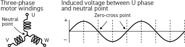
As reference information, we show the induced voltages and zero-cross points at different rotor positions for the U phase, V phase, and W phase in the case of three-phase star connections (with the rotor turning counterclockwise).

The above concludes our explanation of the problem addressed here of how we can know the rotor position if we know the induced voltage.
To summarize:
・The induced voltage in a brushless motor occurs due to changes in the amount of magnetic flux passing through the windings (teeth).
・The windings (teeth) are used as a reference to indicate the position of the rotor.
・The amount of magnetic flux passing through the windings (teeth) is determined by the rotor position.
・By observing the induced voltage waveform, the position of the rotor relative to the windings can be known.
Teacher Sugiken’s Motor Library
Teacher Sugiken’s Motor Driver Dojo
- [Episode 1] I Can See Them! Motor Fairies
- [Episode 2] Sugiken appears! The first step to becoming a super engineer
- [Episode 3] All of Sudden, a Rival Appears for Ichinose Manabu!?
- [Episode 4] A Sudden Closeness?! New Things the Two Have in Common
- [Episode 5] Passion! Which Thoughts Did Ichinose Sense from Ninomiya?
- [Episode 6] Test showdown! A serious battle between Ichinose and Ninomiya!
- [Episode 7] This Is Just the Beginning! Ichinose and Friends’ Motor Driver Dojo
- [Episode 8] The First Meeting! Lessons Learned in a Real Setting
- [Episode 9] A Shortcut to Becoming a Super Engineer!? Learning from the User’s Perspective
- [Episode 10] Beyond the Questions! What Engineer Ichinose Learns
- [Episode 11] Learning And Growing: It’s Not Just About Turning the Motor!
- [Episode 12] To the Next Stage! The Door To Becoming a Super Engineer Opens
An Introduction to Motors
Brushless Mortor Driver
Motor Q&A