
[Episode 12] To the Next Stage! The Door To Becoming a Super Engineer Opens
2025.11.14
Summary of the Previous Episodes
Having gained an understanding of motor driving and protection, Ichinose and Ninomiya realize their own personal growth.
They learned the importance of understanding the condition of a motor from Sugiken’s explanation.
Ichinose imagines himself as a future super engineer, and is further motivated.
Character Introduction
 Ichinose (the protagonist) is a new engineer. He has been aiming to become an engineer since he was in middle school, and finally joined ROHM. He is so passionate that he forgets to eat and sleep while studying on motor drivers. Currently, only Ichinose can see Dora and Tako.
 Ninomiya is in the same year as Ichinose. Her grades are always at the top. She has a strong personality, but she is also a hard worker and has a high opinion of Ichinose. She is in secret a big fan of Sugiken.
 Teacher Sugiken is a super engineer at ROHM. He is usually kind, but he is passionate and takes pride in his work as an engineer. Sugiken used to be able to see Dora and Tako, but now he can’t.
 Dora is a motor driver fairy who loves people who are passionate about motors. He has a crush on Tako, but is always at the mercy of the insensitive Tako.
 Tako is a motor fairy and childhood friend of Dora. She is knowledgeable about motors, and her knowledge surpasses that of Dora. Although she is a reliable older sister, she is insensitive when it comes to love, and is unaware of Dora’s feelings.
Sugiken’s Profile:
Mr. Sugiken works as an associate fellow at ROHM’s Motor LSI Division. He provides various technical advice on motor driver IC development, develops new driving algorithms to improve motor characteristics, and also serves as a lecturer at internal and external study sessions on motor technology and holds technical lectures.
Knowledge Required for Development


Thus far in the Motor Driver Dojo, I have covered the basics of motor drivers: the rotational principles of brushless motors, motor driving, driving circuits, and motor characteristics (output, efficiency, noise, reliability). While this knowledge is essential for developing motor drivers, overcoming technical difficulties and undertaking more advanced development require broader and deeper expertise.
Moving forward, I will be explaining the deeper knowledge that you will need to accumulate as a higher-level engineer, knowledge that rests upon basic knowledge of motor drivers.
Contents of Episode 12
- ・Knowledge Hierarchy and Development Flow
- ・Knowledge of Electrical Circuit
- ・Knowledge of Structures and Materials
- ・Practical Knowledge
- ・Applied Knowledge Relating to Driving
Knowledge Hierarchy and Development Flow
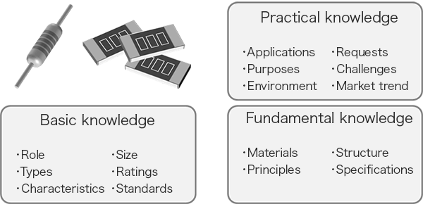
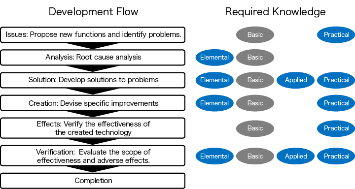
Knowledge relating to technology and components has layers. For example, consider a resistor: its role, characteristics, and ratings are considered basic knowledge. Possessing this basic knowledge means you “know” the resistor. However, when actually using a resistor, knowledge from the user’s perspective—such as its applications, operating environment, requirements, and challenges—becomes necessary. To achieve deeper understanding, solve problems, and lead development to success, fundamental knowledge about materials, principles, and structure is required. Let’s summarize the hierarchy of knowledge needed to progress from merely “knowing” something to deeply understanding and being able to apply and utilize it.
The same applies to motor drivers. Developing motor drivers also requires basic knowledge, practical knowledge, and fundamental knowledge. Additionally, knowledge about the motors themselves that the motor drivers drive is essential.
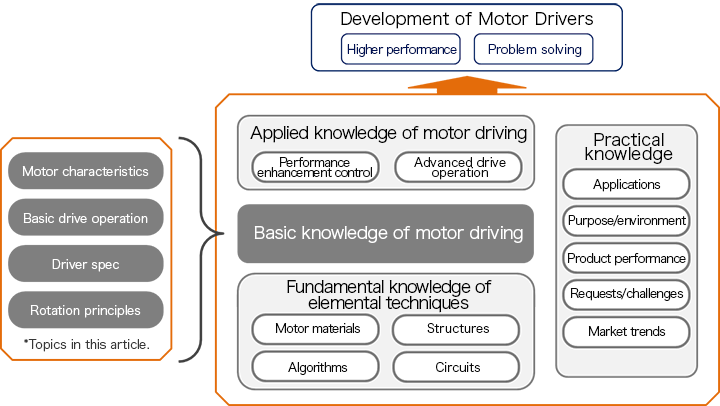
Up to this point in the Motor Driver Dojo, I have explained basic knowledge of motor drivers. This basic knowledge is essential not only for motor drivers themselves but also in order to comprehend peripheral knowledge.
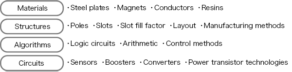
This peripheral knowledge includes the elemental technologies of brushless motors, practical knowledge about motors and motor drivers, and knowledge concerning the application of motor driving systems. Knowledge of elemental technologies includes motor materials, structures, control algorithms, and circuit technologies. Learning this knowledge will enable you to improve motor driver performance and will aid in analyzing and resolving issues.
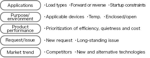
Practical knowledge includes knowledge of applications, motor purposes and environment issues, product performance, requirements and challenges, and market trends. This knowledge will serve as indicators and decision-making factors for determining motor driver specifications.
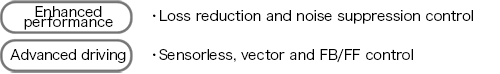
Applied knowledge of motor driving includes performance enhancement control and advanced driving techniques. These are essential practical technologies built upon basic motor knowledge and elemental technology of motors.
Developing motor drivers requires that you understand these concepts and appropriately combine them. Without this integrated knowledge, it is impossible to connect the processes shown below—relating to challenges, factors, improvements, creation, effects, and verification—and complete development. In the Motor Driver Dojo, I have given you the basic knowledge you will need to link these elements. In this final article of the Dojo, I will explain several of these broad and deep knowledge areas that will rest upon the foregoing basic knowledge.
Knowledge of Electrical Circuits
Hall elements
In my talk on IC Hall Elements (Hall ICs) in Brushless Motors in episode 2, I talked about how Hall elements are used to detect the magnetic poles of permanent magnets in the rotor and to judge the rotor position, and about how the detection signals (the output voltages) are proportional to the magnetic flux density passing through the Hall elements. In addition to this basic information, you should also understand that the output voltage characteristic of a Hall element is affected by the material, the size of the current, and the temperature.
For example, the material used in the element affects the electron mobility and the band gap (see the table below). The electron mobility affects the sensitivity of the Hall element, and the band gap affects the temperature characteristics. By “sensitivity” I mean the size of the output voltage when a given current is passed through the element and the element is placed in a magnetic field of a certain strength (the higher the sensitivity, the higher the output voltage). The sensitivity changes with temperature though. And even when the magnetic field is the same strength, the output voltage will rise in proportion to the current flowing in the device.
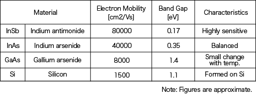
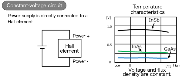
The graph below shows the temperature characteristics of the output voltage for three kinds of Hall elements, based on indium antimonide (InSb), indium arsenide (InAs), and gallium arsenide (GaAs).
These characteristics describe the behavior when the Hall element is used in a circuit configuration that we would call a constant-current circuit. As you can see from the graph, at room temperature (25°C) and below, InSb has high sensitivity and is capable of high output, but as the temperature rises, the output voltage falls rapidly. GaAs is inferior to InSb with respect to sensitivity, but the change with temperature is small. And we might say that InAs strikes a balance between these two.
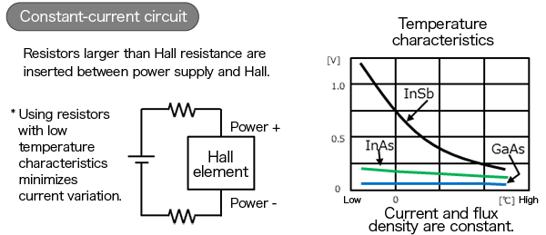
In order to suppress such changes in temperature characteristics, you can use what is called a constant-voltage circuit configuration. The resistance value of a Hall element changes with temperature. For example, in the case of an InSb element the resistance value falls considerably as the temperature rises, so that the current increases. By applying a constant voltage to cancel drops in the output voltage, you can get a nearly constant output. However, you need to be careful using this method: although changes in the output voltage are suppressed, the current being passed changes dramatically with temperature.
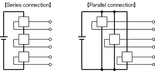
In the above circuit diagram, there is only one Hall element, but in a three-phase motor, a number of Hall elements may be used. In this case, in the design stage you’ll have to choose between series connections and parallel connections to connect the Hall elements to the power supply.
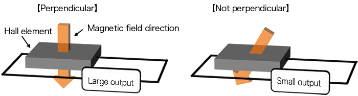
The relationship between the magnetic field direction and the Hall element position (inclination) is also important. The output voltage is different when the magnetic field direction is perpendicular to an element and when it is not perpendicular.
The knowledge you’ll need to appropriately handle Hall elements will be useful when you need to study the specs for Hall signal input terminals in a motor driver, problems relating to signal accuracy (positional shifts), noise processing, and power consumption.
Power transistors
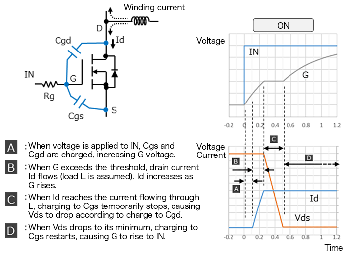
In this Motor Driver Dojo, my explanations have mostly assumed N-type MOSFET power transistors (in the section on Power transistors in episode 10). MOSFETs turn on and off according to the voltage across the gate and the source. The switching speed affects power transistor losses and noise occurrence, and so the switching speed is adjusted by inserting a resistor and capacitors at the gate.
Let me go into a little more detail about switching operation. The diagrams below show the operation when a voltage is applied to IN and a MOSFET is turned on. The horizontal axis of the graph represents time. Here I’ll assume that the winding current is already flowing in the direction indicated in the circuit diagram; before the MOSFET turns on, it’s taken to be flowing in the upward direction in the diagram. In this state, when the voltage is applied to IN, operations occur in the order A, B, C, D shown below, after which the transistor turns on. The turn-off operation is the reverse of this.
When you have understood this operation, you’ll know that in order to adjust the Vds and Id switching speeds (the slopes in the graph) during circuit design, you’ll need to study the values of the resistor and capacitor connected to G and the voltage at IN.
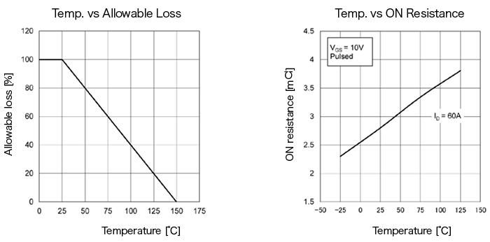
You must also be aware that MOSFET characteristics change with temperature. For example, the allowable loss decreases with rising temperature, while the on-resistance rises as the temperature rises. If you know about these changes in characteristics, they will be useful to you when designing for overheating protection and current limiting.
Other knowledge that you will need when designing power transistor peripheral circuits includes the fact pertinent to performance that dead times are related to deformation of conduction waveforms and affect noise levels, and, where reliability is concerned, information relating to the phenomena known as gate oscillation and self turn-on.
Boosting circuits
The boosting circuits I’m referring to here are circuits that create the power supply needed to turn on high-side N-type MOSFETs (see the part on Level shifters in episode 10). I’ll briefly describe charge pump circuits and bootstrap circuits, which are often used in motor drivers.
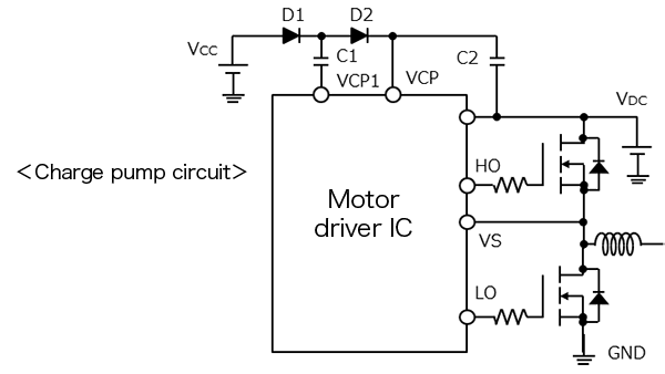
A charge pump circuit has the configuration shown below (here only the power transistors for one phase are shown). In this circuit, VCP1 periodically switches between GND potential and the VDC voltage. When VCP1 is at GND potential, C1 is charged by the VCC voltage, and when VCP1 goes to the VDC voltage, C2 is charged by this voltage. By repeating this operation, the voltage VDC+VCC is constantly applied to VCP. When the motor driver IC outputs this voltage as HO, the high-side power transistor turns on.
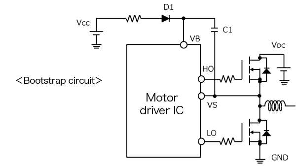
A bootstrap circuit is configured as shown below (this is for one phase; for three phases, you’d need three circuits like this one). In this circuit, first the low-side power transistor turns on, and as a result VS goes to GND potential, upon which C1 is charged by the VCC voltage. This becomes the voltage VB. When the motor driver IC outputs the voltage VB as HO, the high-side power transistor turns on. This voltage VB is generated with reference to the source potential of the high-side power transistor (VS in the figure). Because of this, even when the high side turns on (with the low side off) and VS goes to the VDC voltage level, VB is at voltage VDC+VCC, and the on state is maintained.
In reality, the voltage drops due to the diodes and the voltage drop across the on-resistance of the MOSFET affect the charging voltage, but I’m omitting explanations of these.
When we compare these two circuits, the charge pump circuit can charge C1 and C2 at any time by changing the VCP1 potential through the IC. In the bootstrap circuit, on the other hand, if there isn’t enough time to send VS to GND potential, C1 can’t be charged. However, in the bootstrap circuit the VCC voltage is superposed on the VS reference voltage, and so we can conclude that the power supply is more stable when turning on the high-side power transistor. You’ll need to design your optimal boosting circuit taking into account the different numbers of components as well.
In a boosting circuit, the VCP1 frequency design affects electrical noise, and design features relating to drops in charging voltages for C1 and the like affect the power transistor on/off stability.
Knowledge of Structures and Materials
Numbers of poles and slots
In my discussion of The Number of Poles and Number of Slots in a Motor in episode 2, I explained how motors can have different numbers of poles and slots. Here I’d like to dive into this a bit deeper.
In the basic configuration of a three-phase brushless motor, there are two poles and three slots (2:3 ratio), but configurations such as four poles and six slots, or eight poles and 12 slots, are also possible. A motor with a smaller number of poles has a smaller number of electrical periods per revolution, and so is better suited to high-speed applications. Motors with larger numbers of poles have smaller mechanical angles relative to the electrical angles, and so are well-suited for applications in which precise position control is required.
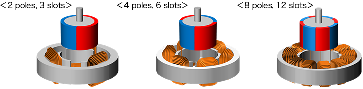
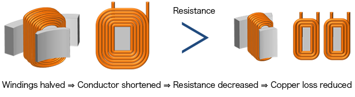
The diagram below shows the windings for motors with six slots and 12 slots. If the number of slots is double, the number of windings per tooth can be reduced by half. Often the windings are wound so as to overlap, as in the diagram below, but the more the windings overlap, the larger becomes the windings diameter, and so in order to obtain one winding, a longer length of conductive wire becomes necessary. This also means that the more the wires overlap, the greater is the increase in the resistance value. In a 12-slot design which makes possible small winding diameters, the resistance value can be kept low, copper losses are reduced, and motor efficiency can be boosted. The perpendicular-direction length is also suppressed, contributing to a thinner motor design.
However, in a many-poles, many-slots motor, deviations in the mechanical angle, converted into the electrical angle equivalent, can be large. And so when designing for controllability, you’ll have to take into account the fact that deviations in Hall signals can be considerable.
In addition to 2:3 ratios of poles to slots, motors can also be configured with for example 8 poles and 9 slots, or 10 poles and 12 slots. In motors with such a configuration, the value of what is called the winding factor changes. The winding factor is calculated by multiplying a short-pitch factor by a distribution factor.
The short-pitch factor is calculated by converting the magnet widths and the teeth tip widths into an angle and using trigonometric functions, and the greatest possible value is 1 (see the diagrams below). The distribution factor is calculated from the phase difference of the magnet opposing the coils of each phase (if there are 12 slots, then there are four coils per phase). This phase difference is roughly equal to the phase difference of the emf voltage generated by each. If there is no phase difference, 1 is used. The closer the winding factor is to 1, the more effectively the magnet is being used, and the motor efficiency tends to be higher.
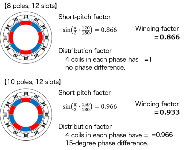
Here, the winding factor is 0.866 for eight poles and 12 slots, and is 0.933 when there are 10 poles and 12 slots, so we can expect higher efficiency for the 10-pole, 12-slot configuration. However, apart from efficiency considerations, there are also such difficulties to consider as the complexity of winding processes, tendencies towards electrical imbalance, and uneven forces brought to bear on the stator.
Where the motor driver design is concerned, if the winding currents can be reduced by raising the motor efficiency, then it may be possible to obtain more leeway with respect to the allowable losses in the power transistors. Even so, the design will need to consider the occurrence of electrical imbalances.
Surface permanent magnet rotors and interior permanent magnet rotors
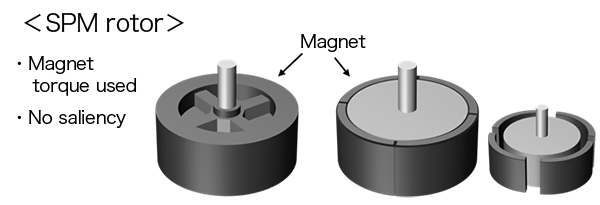
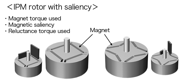
Inner rotor-type brushless motors may have either surface permanent magnet (SPM) or interior permanent magnet (IPM) type rotor structures. SPM rotors have permanent magnets positioned on rotor surfaces; IPM rotors have permanent magnets positioned within them, and are provided with magnetic saliency. Motors using such rotors may be called SPM motors and IPM motors. This should not be confused with the term IPM appearing in my talk on Motor Driver Configuration in episode 10, where it is an abbreviation of intelligent power module, referring to an IC that incorporates a level shifter and power transistors in a single package.
An SPM rotor may be formed from resin magnets, or may have magnets affixed to an iron core. Because the surface is covered with permanent magnets, there is no magnetic saliency, and the magnet torque alone is used to run the motor.
An IPM rotor has permanent magnets embedded within an iron core. The permanent magnets are arranged so as to result in magnetic saliency, and both the magnet torque and the reluctance torque are utilized. The optimal ratio of the two types of torque will differ depending on the motor output and size, and so various arrangement methods have been proposed. An IPM motor designed to enable effective use of both the magnet torque and the reluctance torque will generally have higher maximum efficiency than an SPM motor.
In driving control of these two types of motor, you need to understand the differences in the optimum current phases (see the diagrams below). The optimum current phase for obtaining magnet torque in an SPM motor is the phase at which the winding field is created at an electrical angle of 90° relative to the rotor magnet. In an IPM motor, on the other hand, the optimum current phase to obtain reluctance torque is the phase at which the winding field is generated at 45° to the iron core with magnetic saliency. For this reason, in an IPM motor, the winding field must be generated at the position at which the sum of the two torques is maximum.
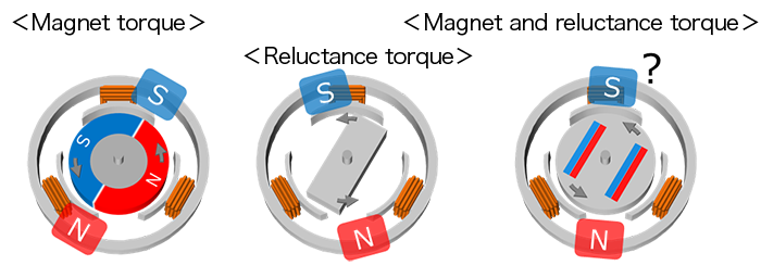
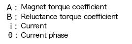
Torque can be represented by the following simplified formula using coefficients. The term that includes A is the magnet torque, and the term that includes B is the reluctance torque. Using this equation, the current phase θ at which the torque T is maximum can be derived. However, you need to remember that A and B will change depending on the structure of the IPM rotor, and also that the magnet torque is proportional to the first power of the current while the reluctance torque is proportional to the square of the current, so that the optimum current phase will differ depending on the size of the output torque.
\(T = A \cdot i \cdot \cos\theta + B \cdot i^2 \cdot \sin 2\theta\)
Current phase control is important in order to achieve high efficiency from an IPM motor. Also, you need to thoroughly understand that the differences in magnet positioning in SPM and IPM rotors will influence rotor position detection by Hall elements.
Permanent magnets
Permanent magnets are structural members that greatly affect the characteristics of a brushless motor. They are mainly categorized by the magnet material, the molding method, and the magnet orientation.
Magnet materials include neodymium and ferrite; they all differ in residual flux density, coercivity, temperature characteristics, and other properties. Neodymium is a rare earth material, whereas ferrite has iron oxide as its main component, and so it is easily obtained.
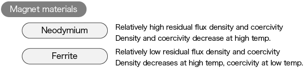
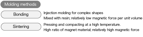
Classified by molding method, there are mainly bonded magnets and sintered magnets. A bonded magnet is fabricated by mixing a magnet material and a resin material, and using injection molding to produce a magnet with the desired shape. A sintered magnet is formed by sintering and compacting magnetic powder. Because there is sintering shrinkage, sintering can be called a magnet manufacturing method that makes dimensional precision difficult to attain. Sintered magnets tend to have higher magnetic force. Neodymium and ferrite can also be used as magnet materials.
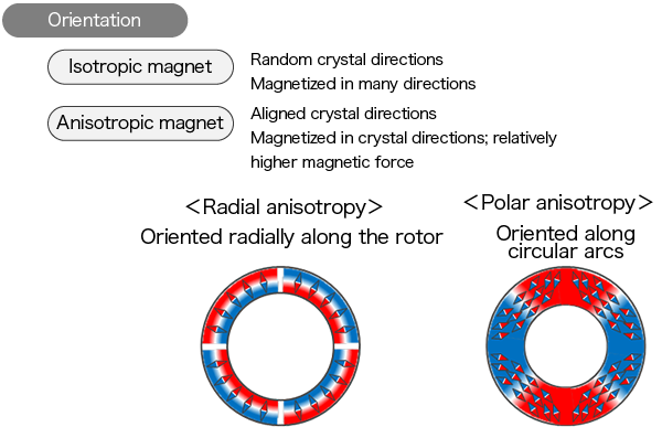
Orientation indicates that the directions of the crystals in the magnet material are aligned. A crystal has directions in which magnetization is easy, and directions in which it is difficult. As a result, the characteristics of a magnet are different when the crystal directions are aligned and when they are not aligned.
A magnet in which directions are not aligned (not oriented) is called an isotropic magnet. Such a magnet can be magnetized in many different directions.
A magnet in which crystal directions are aligned (oriented) is called an anisotropic magnet. Orientation is performed when the magnet is formed. Although an anisotropic magnet can achieve greater magnetic force than an isotropic magnet by magnetizing along the orientation direction, it is difficult to change the magnetization direction after molding. Anisotropy may have an orientation that is called either radial anisotropy or polar anisotropy (see figure below). Rotors with radial anisotropy are suitable for square-wave magnetization; those with polar anisotropy are better suited to sinusoidal magnetization (for more on magnetization waveforms, see Induced Voltage Waveforms in Brushless Motors in episode 4).
These differences in characteristics affect motor control. For example, differences in coercivity will impact how you think about current limiting, and reduced magnetic flux densities at high temperatures will be related to detection of emf voltages and Hall signals. Molding methods and orientation are related to variation in magnetization and deformation of emfs, and so you’ll need to consider motor control from the standpoint of torque pulsation.
Practical Knowledge
Fan loads
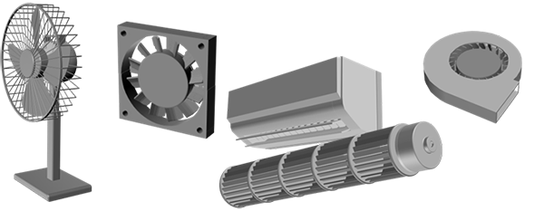
One use of motors is in blower fans. Fans are used in many different forms and guises—in cooling fans and ventilation hoods, cooling equipment for electrical systems such as personal computers, and blower fans for air conditioners. Motor driver ICs are widely used to run such fans.
Fans to be controlled by motors (motor drivers) have the following characteristics.
-
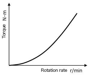
The torque required to turn the fan is proportional to the square of the rotation rate.
When the torque increases as the square of the rotation rate, the motor current increases similarly. Moreover, the output increases as the third power, and copper losses increase as the fourth power. The applied voltage and the rotation rate are not in a direct proportional relationship.
-
Inertia is present (at turn-on, turn-off)
Due to inertia, torque is necessary to cause acceleration, and when the motor is turned off, because of inertia the motor doesn’t stop right away. Rapid acceleration is not regarded as important for a fan or an air conditioner, but when air-cooling a CPU or in other applications it may be important to reach the target rotation rate within a given time. You should also remember that after a motor has been turned off, an emf will occur intermittently.
-
Inertia is present (during constant-speed operation)
Due to inertia, a force acts to continue rotation at constant speed. Hence even when there are changes in the motor output torque or when there are external disturbances, the motor driving control can be designed assuming that, to at least some degree, the rotation speed will be maintained.
-
Fixed rotation direction
Excepting only some specially designed models, the rotation direction of a fan is constant. A motor driving control system can be designed assuming that there are no operations to frequently change the rotation direction.
-
Wind sound is present
When a fan rotates, the sound of wind is generated; this sound grows louder as the rotation rate increases. Other sounds may be masked by this wind sound and so may no longer be regarded as a problem.
-
Fans may be rotated by or affected by outside wind
There are fans that are installed in environments where they may be rotated by outside wind. Motor driving may need to be started from this state. In such a situation, startup from a state of rotation in the opposite direction may also be needed. You also have to consider the possibility of changes in the torque due to headwinds or tailwinds during fan rotation.
-
Wind hitting the motor
In a construction in which wind from the fan hits the motor, the motor may be cooled. However, if it is warm air hitting the motor, the motor may be warmed instead.
-
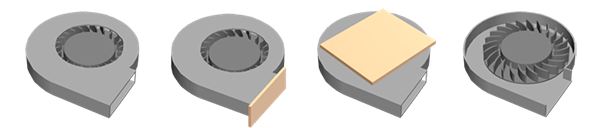
Load torque changes with changes in the air flow
Should the path of air flow be blocked or guides be removed, the rotation rate-torque characteristic curve for the fan will change. Also for fan-motor units such as those shown below, the characteristics may be different for the motor when incorporated into the fan and for the isolated motor.
When designing a driver for a motor that will be used to rotate a fan, you’ll need to understand the characteristics and features I’ve mentioned above before going on to study such issues as the driving method, conduction waveform algorithms, noise, efficiency, and temperature protection.
Applied Knowledge Relating to Driving
Motor control
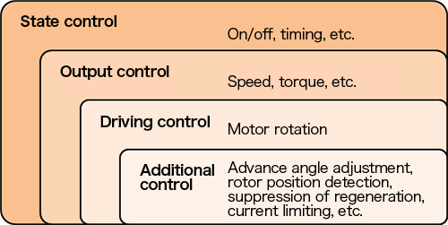
There are a number of levels to brushless motor control. The conceptual diagram below summarizes the levels; on the uppermost level are motor on/off control and timing control (state control). This is mainly handled by the controller of the product in which the motor is mounted. Next are speed and torque control and rotor angle (position) control (output control); after this is motor driving control. Here the waveforms of voltages applied to the windings and the timing are controlled, and control is executed to cause the motor to actually produce a torque. Among this driving control, there are also advance angle control and rotor position detection as additional control to enhance performance.
The simplest motors are only provided with state control and driving control. If you want to add rotation rate and rotation angle management, output control should be added. And in order to boost motor performance and functionality, you could also study additional control to use with driving control.
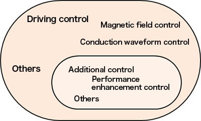
Among the above control levels, in this Dojo I’ve explained the basic parts of “driving control” and “additional control”. From here, we’ll move onto broader, deeper content. Where driving control is concerned, I’ll be introducing “magnetic field control methods” and “conduction waveform control”; as for additional control, I’ll be talking about “control for enhanced performance”.
Examples of magnetic field control methods
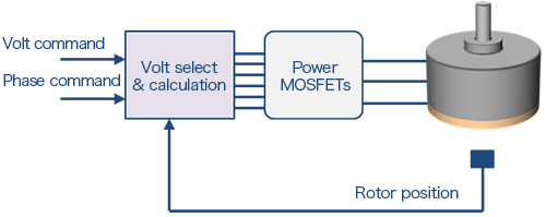
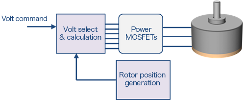
Voltage direction control
This is a method in which the motor driver determines the position of the rotor, and controls the direction of the voltage to apply to the windings according to the position. You could call this a method in which the rotor position information is converted as-is into a conduction waveform, and so the control algorithm is relatively simple. It’s a method that is used by quite a lot of motor driver ICs. Here in this Dojo, I’ll be assuming this method in my explanations.
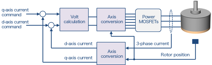
Vector control (FOC)
This is a method in which the motor driver determines the rotor position, and executes control to create a magnetic field in a direction in accordance with the rotor position (field oriented control: FOC). Control of the magnetic field direction involves controlling winding currents: the voltages that should be applied to windings so as to cause desired currents to flow are calculated. For this reason, in general the resistance values and inductances of the motor windings, the induced voltage constants, and other parameters are needed in order to calculate voltages. Torque control is simplified by using current commands, making this suited to use in position control. And current values and phases can be adjusted, making the method apt for use in controlling the IPM motors I mentioned above. On the other hand, various parameters must be used to calculate voltages, and so algorithms are comparatively complex, and in many cases a microcomputer must be used for the motor driver.
Forced synchronous driving
In this method the motor driver rotates a magnetic field at an arbitrary rotation rate without determining the rotor position. The rotation rate and the current (voltage for application) are adjusted such that the rotor can follow the magnetic field. This method can be used to continuously run a motor, but because there are problems with respect to both efficiency and reliability (loss of synchronization), it is often used as a temporary driving method in circumstances under which the rotor position cannot be determined. One such set of circumstances in which the rotor position is unknown is upon startup in sensorless driving. A voltage for application can be created by generating a virtual rotor position, and so this method can be used with either a motor driver IC or with a microcontroller.
Examples of conduction waveform control
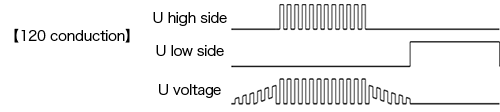
120-degree square-wave conduction
This is one conduction waveform for voltage direction control; rotor positions are divided into six intervals, and the voltage application direction is changed successively. The waveforms can easily be generated from the signals of three Hall elements and PWM signals. However, torque pulsation is large compared to other conduction methods.
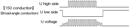
150-degree conduction
This is another conduction waveform for voltage direction control, and is also called broad-angle conduction or trapezoidal conduction. Rotor positions are divided into 12 intervals, and the voltage application direction is changed successively. The waveforms cannot be generated by a simple logic circuit taking as input the signals from three Hall elements, and a multiplication circuit is necessary. Using a multiplication circuit, angle signals such as 30 degrees, 10 degrees, 1 degree, and the like are generated from a signal with an electrical angle of 60 degrees. Depending on the conduction waveform, torque pulsation can be made smaller than when using 120-degree square-wave conduction.
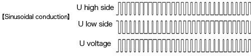
Sinusoidal conduction
This is still another conduction waveform for voltage direction control, in which rotor positions are divided into an arbitrary number of intervals, and the voltage application direction is changed successively. The smaller the time intervals are made, the more nearly a sinusoidal waveform is approached, and the better the expected suppression of torque pulsation. As with 150-degree conduction, a multiplication circuit is used for finer time intervals. The diagram below shows waveforms when PWM control is used to obtain a pure sinusoidal waveform. In addition to this, there are many other sinusoidal conduction waveforms, such as two-phase modulation sinusoidal waveforms (refer to Synchronous Rectification in episode 7).
Examples of performance enhancement control
Automatic Adjustment of Advance Angle
This control enhances the performance of voltage direction control by automatically adjusting the advance angle (phase), as I explained in Advance Angle Control of a Brushless Motor in episode 7 to ensure optimal efficiency. There are several automatic adjustment methods. One method detects the phase of the winding current during sinusoidal conduction and adjusts the voltage phase to align it with the desired position. Another method varies the voltage phase according to certain state values such as rotational speed, current, or the applied voltage command. In the latter method, the ratio between the state values and the advance angle are often predetermined (adjusted according to each motor’s specifications). Implementing these controls requires knowledge of the phase relationship between the applied voltage and winding current, as well as of current detection, circuitry, and control algorithms. Note that since vector control fundamentally adjusts the current, the concept of advance angle adjustment is not usually considered.
Detection of Initial Rotor Position
This control is used in sensorless driving control, which does not employ position detectors such as Hall sensors. A widely used method involves passing an instantaneous current through the winding that does not change the motor rotational state, then detecting the current position of the rotor based on the behavior of the current and winding voltage at that moment. This control requires knowledge of the changes in the motor winding inductance due to the magnetic flux from the permanent magnet, as well as of the magnetic saturation phenomenon of the iron core.
Suppression of Regeneration
This control suppresses regeneration. While motor regenerative energy can be utilized, increased supply voltage may negatively impact reliability if the power supply circuit is not designed to handle power absorption. To suppress regeneration, the techniques of lowering the supply voltage and optimizing the switching method of the power transistors are being investigated (Synchronous Rectification in episode 7). This control requires knowledge of motor inertia, the induced voltage generation mechanism, and PWM control.
Current Limiting
This control technique primarily enhances the performance of voltage direction control by limiting the current passing through the motor driver power transistors and motor windings. Current-limiting methods include turning off the voltage supply for a set duration or adjusting the duty cycle in PWM control, when the current exceeds the predetermined threshold value. Since there are also several methods of switching off the voltage supply, the most appropriate method is selected based on the intended use. These control methods require knowledge of losses, heat generation, circuitry, PWM control, and control algorithms.
Up to this point, I have explained motor control methods individually, but the control methods are interrelated. This includes which controls can be added to which, whether they need to be added, and whether there are any conflicts. For example, as I mentioned earlier, there is no need to add automatic advance angle adjustment control to vector control. Furthermore, 120-degree square wave is impractical for implementing the vector control (in vector control, the conduction waveforms seen in voltage direction control are not discussed).
Therefore, when configuring motor drive controls (motor drivers), you need to understand the purpose of each control, and you must combine them so as to overcome any challenges.
This concludes my introduction to the knowledge required for developing motor drivers. The hierarchical structure (levels) of knowledge presented here is just one approach; technology can be categorized from different perspectives. However, the fundamental truth remains unchanged: developing something new or solving challenges requires broad and deep knowledge, along with the technical development skills to integrate that knowledge. I hope this guide serves as foundational knowledge to help you continue expanding your motor-related knowledge and skills.
Key points of this article
・Knowledge of motor drivers encompasses not only basic knowledge but also knowledge of elemental technologies, practical knowledge of motors and motor drivers, and applied knowledge of driving systems.
・Building upon basic knowledge and deepening understanding at a more advanced level enables problem-solving and leads to successful motor driver development.
・Deep knowledge of pole and slot numbers, SPM, IPM, and permanent magnets can be reflected in the design specifications of motor drivers.
・Understanding fan loads enables optimization of motor driver specifications.
・Motor control also encompasses several levels of control, including on/off control, speed control, driving control, and performance enhancement control.
・Controls at each level are interrelated, so it is necessary to understand the meaning of each control method and address methods according to purposes and goals.
・By connecting knowledge accumulated in each layer, the development process—covering challenge, analysis, improvement, creation, effects, and verification—can be completed.


Teacher Sugiken’s Motor Library
Teacher Sugiken’s Motor Driver Dojo
- [Episode 1] I Can See Them! Motor Fairies
- [Episode 2] Sugiken appears! The first step to becoming a super engineer
- [Episode 3] All of Sudden, a Rival Appears for Ichinose Manabu!?
- [Episode 4] A Sudden Closeness?! New Things the Two Have in Common
- [Episode 5] Passion! Which Thoughts Did Ichinose Sense from Ninomiya?
- [Episode 6] Test showdown! A serious battle between Ichinose and Ninomiya!
- [Episode 7] This Is Just the Beginning! Ichinose and Friends’ Motor Driver Dojo
- [Episode 8] The First Meeting! Lessons Learned in a Real Setting
- [Episode 9] A Shortcut to Becoming a Super Engineer!? Learning from the User’s Perspective
- [Episode 10] Beyond the Questions! What Engineer Ichinose Learns
- [Episode 11] Learning And Growing: It’s Not Just About Turning the Motor!
- [Episode 12] To the Next Stage! The Door To Becoming a Super Engineer Opens
An Introduction to Motors
Brushless Mortor Driver
Motor Q&A