Motor|Basic
Characteristics of Brushed DC Motors
2022.03.09
Points of this article
・When a torque is applied, the rotation rate drops by a constant amount.
・When the power supply voltage is raised, the rotation rate rises.
・When a torque is applied, the motor current increases by a constant amount.
・At maximum torque, which means zero rotation rate, the motor current is maximum.
table of contents
Up until the previous article, we had explained the principles of brushed DC motors. Here we describe the basic characteristics of brushed DC motors.
Characteristics of Brushed DC Motors
Put in simple terms, when a power supply voltage is applied to a motor, a current flows and the motor rotates; but the characteristics of the power supply voltage, the rotation rate, the torque, and other quantities are all interrelated. We explain these relations using an equivalent circuit and equations for a brushed motor.
●DC equation for the closed circuit: ![]()
*Ea: Power supply voltage, R: Armature resistance,
Ia: Motor current, Ec: Motor induced voltage
The power supply voltage Ea is equal to the induced voltage Ec plus the product of the armature resistance R and the motor current Ia. The armature resistance has resistance components due to the windings and to the core. That the voltage is equal to resistance times current is precisely Ohm’s law. The induced voltage is the voltage that occurs due to rotation of the motor (electricity generation), and is an additional voltage.
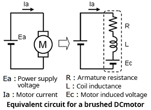
●Motor induced voltage:
![]()
*Ec: Motor induced voltage, Ke: Power generation constant, N: Rotation rate
The motor induced voltage Ec is equal to the power generation constant Ke multiplied by the rotation rate N. Hence the induced voltage of the motor is proportional to the rotation rate.
●Motor torque:
![]()
*T: Torque, Kt: Torque constant, Ia: Motor current
The motor torque T is the torque constant Kt multiplied by the motor current Ia. Hence the motor torque is proportional to the current.
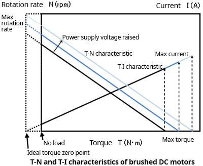
●Relationship between rotation rate and torque:
![]()
The above-described equations for the induced voltage and torque of a motor are summarized, and the relationship between rotation rate N and torque T is illustrated below. Ke and Kt are constants, and so from the equations we can see that: 1) when a torque T is applied, the rotation rate N drops by a fixed amount; and, 2) when the torque T is a fixed value, the rotation rate N rises in proportion to the power supply voltage Ea.
The above relations are summarized in the diagram on the right. The torque-rotation rate (T-N) characteristic is such that when a torque is applied, the rotation rate falls by a fixed amount, that is, the relationship is inverse proportionality. And, when the power supply voltage is raised, the voltage applied to the motor rises, so that the rotation rate increases. The maximum torque occurs when the rotation rate is zero.
The torque-current (T-I) characteristic indicates that when a torque is applied, the motor current increases by a constant amount, that is, increases proportionally. At maximum torque, which occurs at zero rotation rate, the motor current is maximum.
When driving a motor, the driving conditions must be considered based on these relationships.
Motor Parameter Units
A number of motor parameters were introduced in the above explanations. The units in general use for these are as follows.
Rotation rate N: min-1, rpm, rad/s
Torque T: N・m
Power generation constant Ke: V・s/rad, V/rpm
Torque constant Kt: N・m/A
For some parameters, multiple units are used; as the units employed when converting electrical energy into mechanical energy, the N・m, rad/s and V・s/rad units indicated in boldface must be used consistently.
【Download Documents】 Basics of Brushed DC Motors and Drive Methods
Brushed DC motors are the most versatile motors and are used in a great many applications. This handbook provides the basics of brushed DC motors, explaining their construction, principle of operation, characteristics, and driving methods.

Motor
Basic
-
Brushed DC Motor
- Construction of Brushed Motors
- Principle of Rotation
- Power Generation Principle
- Short Braking
- Characteristics of Brushed DC Motors
- Driving Brushed DC Motors with an H-Bridge:Principles
- Driving Brushed DC Motors with an H-Bridge:Switching Output States
- Driving Brushed DC Motors with an H-Bridge:High-Side Voltage Linear Control
- Driving of Brushed DC Motors Using BTL Amplifier Circuits: Linear Voltage Driving
- Driving of Brushed DC Motors Using BTL Amplifier Circuits: Linear Current Driving
- Driving Brushed DC Motors Using PWM Output: Principles of PWM Driving
- Driving Brushed DC Motors Using PWM Output: Current Regeneration Methods in PWM Driving
- Driving Brushed DC Motors Using PWM Output: Losses and Points to be Noted
- Driving Brushed DC Motors Using PWM Output: PWM Driving with an H-Bridge Circuit
- Driving Brushed DC Motors Using PWM Output: H Bridge Constant-Current Driving
- Driving Brushed DC Motors Using PWM Output: Driving in the Form of BTL Amplifier Input
- Single-Switch Circuit Driving and Half-Bridge Circuit Driving
- Driving Circuits for Brushed DC Motors – Summary
-
Stepping Motors
- Structure of Stepping Motors
- Basic Operating Principles of Stepping Motors
- Stepping Motors: Microstep Operation Principles
- Basic Characteristics of Stepping Motors
- Structure and Operating Principles of Hybrid Type Stepping Motors
- Stepping Motor Driving: Bipolar Connections and Unipolar Connections
- Driving 2-Phase Bipolar Stepping Motors: Part 1
- Driving 2-Phase Bipolar Stepping Motors: Part 2
- Driving 2-Phase Unipolar Stepping Motors
- Stepping Motors – Summary
-
3-Phase Brushless Motors
- Structure of 3-Phase Full-Wave Brushless Motors
- Principles of Rotation of 3-Phase Full-Wave Brushless Motors
- Position Detection in 3-Phase Full-Wave Brushless Motors
- Driving 3-Phase Full-Wave Brushless Motors: 120° Commutation Linear-Current Driving with Sensors
- Driving 3-Phase Full-Wave Brushless Motors: Sinusoidal Commutation PWM Driving with Sensors
- Driving 3-Phase Full-Wave Brushless Motors: Advance Angle Control
- Driving 3-Phase Full-Wave Brushless Motors: Maximization of Motor-Applied Voltage
- Driving 3-Phase Full-Wave Brushless Motors: Sensorless 120° Commutation Driving
- Methods of Sensorless 120° Commutation Driving Startup 1: Startup on Detection of Induced Voltage from Synchronous Operation
- Methods of Sensorless 120° Commutation Driving Startup 2: Startup on Detection of Permanent Magnet Stopped Position
- Features and Applications of 3-Phase Full-Wave Brushless Motors ーSummaryー
- What is a Motor?