Motor|Basic
Driving Brushed DC Motors Using PWM Output: Current Regeneration Methods in PWM Driving
2022.07.20
Points of this article
・In PWM driving of a brushed DC motor, voltage application and current regeneration are repeated.
・There are multiple methods of current regeneration using an H bridge; losses differ depending on the regeneration current path.
In the previous article in which the principles of PWM driving of brushed DC motors were explained, current regeneration was based on the method of shorting the motor terminals. But there are other methods of current regeneration, and each of these methods has matters that demand study.
Driving Brushed DC Motors Using PWM Output: Current Regeneration Methods
Below are schematic diagrams used to explain PWM driving principles. Transistors that need not be shown are omitted. (a) shows operation during voltage application, and (b) is current regeneration by shorting the motor terminals.
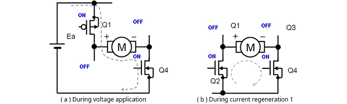
As a matter that should pragmatically be considered, transistors (in this case, MOSFETs) are used for switching in the H bridge, and so for each current path, the on resistance of the transistor must be added as a loss. This is also true for the current regeneration methods described below.
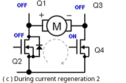
In addition to (b), there are three current regeneration methods. Method (c) is a method in which, from the voltage application state, only Q1 is turned off (Q2 and Q3 remain off; Q4 remains on). The regeneration current in this case passes through the parasitic (body) diode of Q2, which is off, and flows as in (b). In this case, the current path includes the forward voltage VF of the parasitic diode in addition to the on-resistance; consequently, the current is rapidly attenuated. The equivalent average voltage applied to the motor is smaller than the voltage corresponding to the duty cycle by the loss due to the VF component.
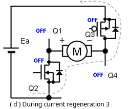
In method (d), all transistors are turned off. In this case the regeneration current flows through the parasitic diodes of Q2 and Q3, which are off. In this path, the VF components of the two parasitic diodes of Q2 and Q3 constitute the loss.
Further, a power supply Ea is present in the current path, acting to pass a current in the reverse direction, so that attenuation of the regeneration current is extremely rapid, and the equivalent average voltage applied to the motor given on the on duty is extremely low. When driving at 50% duty, the equivalent average applied voltage is close to zero. In this case, diodes are present, so that when the current goes to zero, regeneration stops, and no current flows in the reverse direction.
In method (e), the transistors turned on are the reverse of those turned on during voltage application. That is, in this method switching is performed from the voltage-applied state in which Q1 and Q4 are on while Q2 and Q3 are off, to the state in which Q1 and Q4 are off and Q2 and Q3 are on, to enter a reverse-bias state.
In this case also a power supply Ea is present in the current path, acting to pass current in the reverse direction, so that attenuation of the regeneration current is extremely fast; when the regeneration current flows through diodes, regeneration stops when the current reaches zero, but because transistors are on, current flows in the reverse direction.
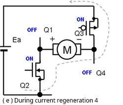
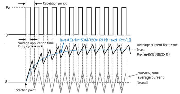
Hence as with method (d), when driving at 50% duty, the equivalent average voltage applied to the motor is zero. At 100% duty, the equivalent average voltage applied is maximum, and for duties between 100% and 50%, the applied voltage can be controlled between the maximum voltage and zero voltage, proportionally to the duty. At duties between 50% and 0%, current flows in the direction opposite the current direction from 100% to 50%. Below are PWM voltage and current waveforms for these conditions.
The losses mentioned briefly in the above explanation will be discussed separately in the next article.
【Download Documents】 Basics of Brushed DC Motors and Drive Methods
Brushed DC motors are the most versatile motors and are used in a great many applications. This handbook provides the basics of brushed DC motors, explaining their construction, principle of operation, characteristics, and driving methods.

Motor
Basic
-
Brushed DC Motor
- Construction of Brushed Motors
- Principle of Rotation
- Power Generation Principle
- Short Braking
- Characteristics of Brushed DC Motors
- Driving Brushed DC Motors with an H-Bridge:Principles
- Driving Brushed DC Motors with an H-Bridge:Switching Output States
- Driving Brushed DC Motors with an H-Bridge:High-Side Voltage Linear Control
- Driving of Brushed DC Motors Using BTL Amplifier Circuits: Linear Voltage Driving
- Driving of Brushed DC Motors Using BTL Amplifier Circuits: Linear Current Driving
- Driving Brushed DC Motors Using PWM Output: Principles of PWM Driving
- Driving Brushed DC Motors Using PWM Output: Current Regeneration Methods in PWM Driving
- Driving Brushed DC Motors Using PWM Output: Losses and Points to be Noted
- Driving Brushed DC Motors Using PWM Output: PWM Driving with an H-Bridge Circuit
- Driving Brushed DC Motors Using PWM Output: H Bridge Constant-Current Driving
- Driving Brushed DC Motors Using PWM Output: Driving in the Form of BTL Amplifier Input
- Single-Switch Circuit Driving and Half-Bridge Circuit Driving
- Driving Circuits for Brushed DC Motors – Summary
-
Stepping Motors
- Structure of Stepping Motors
- Basic Operating Principles of Stepping Motors
- Stepping Motors: Microstep Operation Principles
- Basic Characteristics of Stepping Motors
- Structure and Operating Principles of Hybrid Type Stepping Motors
- Stepping Motor Driving: Bipolar Connections and Unipolar Connections
- Driving 2-Phase Bipolar Stepping Motors: Part 1
- Driving 2-Phase Bipolar Stepping Motors: Part 2
- Driving 2-Phase Unipolar Stepping Motors
- Stepping Motors – Summary
-
3-Phase Brushless Motors
- Structure of 3-Phase Full-Wave Brushless Motors
- Principles of Rotation of 3-Phase Full-Wave Brushless Motors
- Position Detection in 3-Phase Full-Wave Brushless Motors
- Driving 3-Phase Full-Wave Brushless Motors: 120° Commutation Linear-Current Driving with Sensors
- Driving 3-Phase Full-Wave Brushless Motors: Sinusoidal Commutation PWM Driving with Sensors
- Driving 3-Phase Full-Wave Brushless Motors: Advance Angle Control
- Driving 3-Phase Full-Wave Brushless Motors: Maximization of Motor-Applied Voltage
- Driving 3-Phase Full-Wave Brushless Motors: Sensorless 120° Commutation Driving
- Methods of Sensorless 120° Commutation Driving Startup 1: Startup on Detection of Induced Voltage from Synchronous Operation
- Methods of Sensorless 120° Commutation Driving Startup 2: Startup on Detection of Permanent Magnet Stopped Position
- Features and Applications of 3-Phase Full-Wave Brushless Motors ーSummaryー
- What is a Motor?