AC-DC|Basic
What is Forward System?
2015.09.03
Points of this article
・Though more complicated than the flyback system, on the secondary side the forward system operates according to the same underlying principle as in DC-DC conversion using diode rectification (asynchronous).
・As snubber circuits are also used extensively in power supply designs, we need a solid understanding of the underlying principles of those circuits.
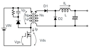
Figure 21. Forward system
Given a relatively simple configuration and easy to control, the forward system represents one of the more popular systems.
In terms of characteristics, the forward system is capable of producing larger-power output when compared with the flyback system, while requiring both an inductor and a flywheel diode (commutation diode: D2). In addition, similar to the flyback system, the forward system can be made into an insulated power supply unit through the use of a optocoupler on the feedback line from the output.
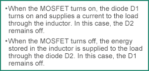
Figure 22
The forward system operates as follows: When the MOSFET turns on, the diode D1 turns on and supplies a current to the load through the inductor. When the MOSFET turns off, the energy stored in the inductor is supplied in the form of a current to the load through the diode D2. Figure 23 shows waveforms for the key nodes.

Figure 23. Forward system: Waveforms for the key nodes
Because the forward system excites the transformer only in one direction, while the transistor is off, the energy stored in the transformer must be released (reset). For this purpose, the forward system requires a reset (snubber) circuit (the RCD located on the primary side of the transformer in Figure 21). Generally a reset circuit is configured using a circuit containing a resistor, a capacitor, and a diode. However, because the energy ends up being lost, basically the utilization efficiency of the transformer may not be very high. In connection with the reset operation, a voltage as much as 1.5 to 2 times the DC input voltage is exerted on the switching transistor (in Figure 23, the VR in the Vp and Vds waveforms). This voltage varies with the snubber resistance and the capacitor. Recently, a system has come into use combining an active clamp that is capable of reducing losses and Vds by recovering the energy that needs to be reset.
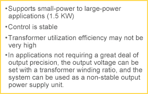
Figure 24
Furthermore, in the case of stepping down, the amount of current on the primary side is low, and the amount of energy trapped in the coils is not all that large. However, when the forward system is used for stepping up, the current on the primary side increases. Since the energy building up in the coils also varies as the square of the current, the energy lost in the reset circuit tends to be large. Consequently, although this circuit is used for stepping down operations, it is rarely used in stepping up applications.
In AC-DC conversions, the switching system is mainly used. Although it can also be used in the transformer system, similar to the flyback system, the use of the forward system is limited to applications that require adequate insulation.
【Download Documents】 Basics of AC-DC Converter and Design Procedures
A hand book for beginners to AC-DC converter design, covering the basics of AC-DC conversion and various conversion methods, as well as the procedures and issues involved in designing an AC-DC converter.

AC-DC
Basic
- AC-DC Basics
- DC-DC Conversion (Regulated) System after Smoothing
- Design Procedure for AC-DC Conversion Circuits (Overview)
- Issues and considerations in AC-DC Conversion Circuit Design
- Summary
- Extra Plus Basic Knowledge
Design
-
Overview of Design Method of PWM AC-DC Flyback Converters
- Isolated Flyback Converter Basics: Flyback Converter Operation and Snubber
- Isolated Flyback Converter Basics: What are Discontinuous Mode and Continuous Mode?
- Want are Isolated Flyhback Convertors?
- Design Procedure
- Isolated Flyback Converter Basics: What is Switching AC-DC Conversion?
- Determining Power Supply Specifications
- Designing Isolated Flyback Converter Circuits
- Isolated Flyback Converter Basics: What are Characteristics of Flyback Converter?
- Designing Isolated Flyback Converter Circuits: Transformer Design (Calculating numerical values)
- Choosing an IC for Design
- Designing Isolated Flyback Converter Circuits: Transformer Design (Structural Design) – 1
- Designing Isolated Flyback Converter Circuits: Transformer Design (Structural Design) – 2
- Designing Isolated Flyback Converter Circuits: Selecting Critical Components ? MOSFET related – 1
- Designing Isolated Flyback Converter Circuits: Selecting Critical Components ? MOSFET related – 2
- Designing Isolated Flyback Converter Circuits: Selecting Critical Components ? CIN and Snubber
- Designing Isolated Flyback Converter Circuits: Selecting Critical Components ? Output Rectifier and Cout
- Designing Isolated Flyback Converter Circuits: Selecting Critical Components ? VCC of IC
- Designing Isolated Flyback Converter Circuits: Selecting Critical Components – IC Settings Etc.
- Designing Isolated Flyback Converter Circuits: Addressing EMI and Output Noise
- Example Board Layout
- Summary
-
Overview of Design Examples of AC-DC Non-isolated Buck Converters
- What are Buck Converters? – Basic Operation and Discontinuous Mode vs. Continuous Mode
- Selection of Power Supply ICs and Design Examples
- Selecting Critical Components: Input Capacitor C1 and VCC Capacitor C2
- Selecting Critical Components: Inductor L1
- Selecting Critical Components: Current Sense Resistor R1
- Selecting Critical Components: Output Capacitor C5
- Selecting Critical Components: Output Rectifying Diode D4
- EMI Countermeasures
- Board Layout and Summary
-
Introduction
- Design Procedure
- IC Used in Design
- Power Supply Specifications and Replacement Circuit
- Synchronous Rectifying Circuit Section: Selection of Synchronous Rectifying MOSFET
- Synchronous Rectification Circuit Section: Power Supply IC Selection
- Troubleshooting ①: Case When Secondary-Side MOSFET Suddenly Turns OFF
- Synchronous Rectification Circuit Section: Selection of Peripheral Circuit Components-C1, R3 at MAX_TON Pin, and VCC Pin
- Troubleshooting ②: Case When Secondary-Side MOSFET Turns On Due to Resonance Under Light Loading
- Troubleshooting ③: Case When, Due to Surge, VDS2 Rises to Above Secondary-Side MOSFET VDS Voltage
- Comparison of Efficiency of Diode Rectification and Synchronous Rectification
- Points to Note Relating to PCB Layout
- Summary
- Synchronous Rectification Circuit Section: Selection of Peripheral Circuit Components-D1, R1, R2 at DRAIN Pin
- Shunt Regulator Circuit Section: Selection of Peripheral Circuit Components
-
Introduction
- Power Supply ICs Used in Design: Optimized for SiC MOSFETs
- Design Example Circuit
- Transformer T1 Design – 1
- Transformer T1 Design – 2
- Selecting Critical Components: MOSFET Q1
- Selecting Critical Components: Input Capacitor and Balancing Resistor
- Selecting Critical Components: Switch Setting Resistors for Overload Protection Points
- Selecting Critical Components: VCC-Related Components of Power Supply ICs
- Selecting Critical Components: Components Related to Power Supply IC BO (Brownout) Pins
- Selecting Critical Components: Components Related to Snubber Circuits
- Selecting Critical Components: MOSFET Gate Drive Adjustment Circuit
- Selecting Critical Components: Output Rectifying Diode
- Selecting Critical Components: Output Capacitors, Output Setting and Control Components
- Selecting Critical Components: Current Sense Resistors and Components Related to Detection Pins
- Selecting Critical Components: Components for Dealing with EMI and Output Noise
- PCB Layout Example
- Example Circuit and Component List
- Evaluation Results: Efficiency and Switching Waveform
- Summary
Evaluation
-
What are Isolated Flyback Converters Performance Evaluation and Checkpoints?
- Overview and important features of a power supply IC used in example performance evaluation
- Design goals and circuits in performance evaluation
- Performance evaluation using an evaluation board: Measurement method and results
- Critical checkpoint: Output transient response and rising output voltage waveform
- Critical checkpoint: Measuring temperature and loss
- Critical checkpoint: Aluminum electrolytic capacitors
- Summary
- Critical checkpoint: Transformer saturation
- Critical checkpoint: MOSFET VDS and IDS, and rated voltage of output rectifier diode
- Critical checkpoint: Vcc voltage
Product Information
FAQ