AC-DC|Basic
Transformer System
2015.09.03
Points of this article
・The transformer system is most basic to the AC-DC conversion process.
・The output voltage just rectified is unregulated and it drops in proportion with increasing the load.
As a method of AC-DC conversion, we will explain a system that is based on a transformer. Figure 3 illustrates the general configuration of the transformer system.
Here we assume that the input voltage is 100VAC. The transformer steps down (transforms) the 100VAC input into an AC voltage from which a desired DC voltage can be produced. This part of operation constitutes an AC/AC conversion. The transformed level (the stepped down voltage generated on the secondary side of the transformer) is set in terms of a winding ratio between the primary and secondary sides of the transformer.
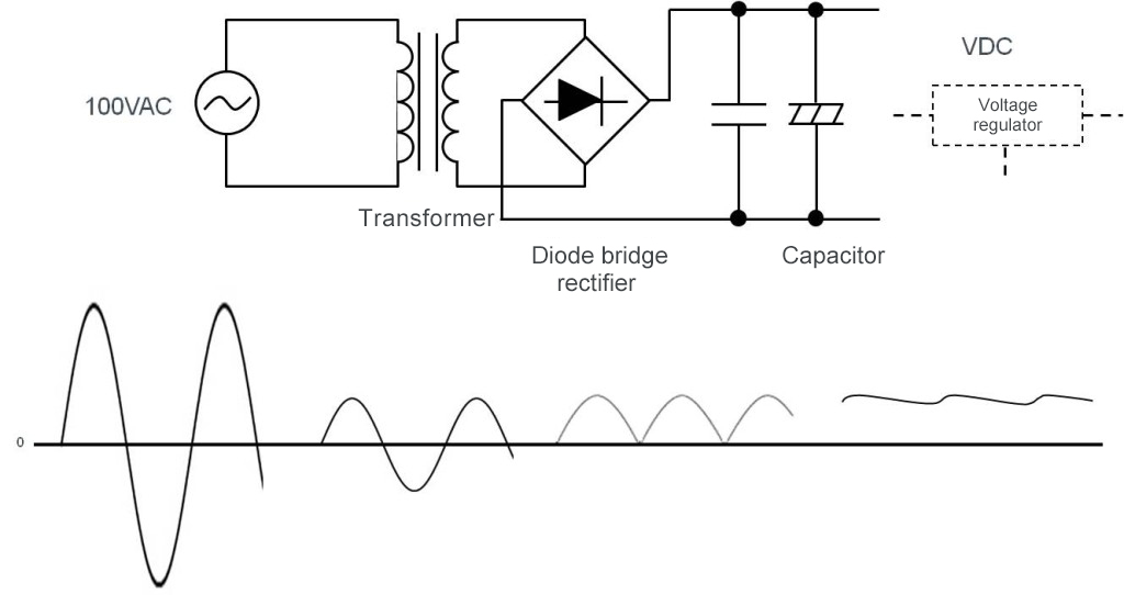
Figure 3. Transformer based AC-DC conversion
If insulation is needed between the input and output sides, a transformer can be used to provide insulation.
The stepped-down AC voltage is converted to DC with a diode bridge rectifier, and smoothed out by a capacitor for final conversion to a DC voltage with small ripples. The rectified DC voltage is equal to the AC peak voltage (AC×√2) minus the forward voltage of the diode.
When regulation of output is not needed, the DC voltage can be used as an output. The initial value of the voltage depends upon the winding ratio in the transformer, and the voltage declines as the load current increases. If regulation is needed, it is performed using a voltage regulator. In this case, the voltage on the secondary side of the transformer must be set to a level suitable for conversion by the regulator.
If the ultimate goal is to create 12VDC, for example, a common approach is to set the voltage after rectification to approximately 18VDC so that it is not too low for proper operation and not too high to minimize losses.
Components used in a transformer system
The figure below shows examples of actual components used in a transformer based AC-DC conversion process.
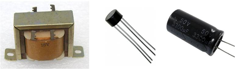
Figure 4. Example of components in transformer based AC-DC conversion. From the left: a transformer, a diode bridge rectifier, and an electrolytic capacitor
For the transformer used for AC/AC conversion, a low-frequency transformer is used since AC frequency is 50 or 60 Hz. Transformers that are designed as power supply units are called power transformers or commercial frequency transformers (commercial transformers). The size (volume) of a transformer may be thought of as being proportional to the output power of the power supply unit. A familiar example is AC adapters, which are supplied in units such that the larger their current capacity the bulkier and heavier the units. The basic structure of a transformer consists of an iron core, and primary and secondary winding wires. A core is commonly made of a silicon steel plate.
A diode bridge rectifier is supplied as a single package containing four diodes connected to perform rectifying. In terms of the shape of a diode bridge rectifier, in addition to the configuration shown in the photograph, there are SIP and DIP with a square package. Four single-unit rectifying diodes may be combined to form a diode bridge. The size of a diode also tends to become large as the amount of allowable current increases.
For a capacitor, basically an electrolytic capacitor is employed. The required capacitance, which varies with the load or allowable ripples, ranges from hundreds to thousands of μF. The larger the supply output power, the larger is also the size of the capacitor.
In a circuit that provides a supply voltage for general electronic circuits, the only component that handles high voltages is the transformer. For other components, a rated voltage matching the specific DC voltage to be supplied must be selected.
The transformer system has been in use most extensively for decades.
【Download Documents】 Basics of AC-DC Converter and Design Procedures
A hand book for beginners to AC-DC converter design, covering the basics of AC-DC conversion and various conversion methods, as well as the procedures and issues involved in designing an AC-DC converter.

AC-DC
Basic
- AC-DC Basics
- DC-DC Conversion (Regulated) System after Smoothing
- Design Procedure for AC-DC Conversion Circuits (Overview)
- Issues and considerations in AC-DC Conversion Circuit Design
- Summary
- Extra Plus Basic Knowledge
Design
-
Overview of Design Method of PWM AC-DC Flyback Converters
- Isolated Flyback Converter Basics: Flyback Converter Operation and Snubber
- Isolated Flyback Converter Basics: What are Discontinuous Mode and Continuous Mode?
- Want are Isolated Flyhback Convertors?
- Design Procedure
- Isolated Flyback Converter Basics: What is Switching AC-DC Conversion?
- Determining Power Supply Specifications
- Designing Isolated Flyback Converter Circuits
- Isolated Flyback Converter Basics: What are Characteristics of Flyback Converter?
- Designing Isolated Flyback Converter Circuits: Transformer Design (Calculating numerical values)
- Choosing an IC for Design
- Designing Isolated Flyback Converter Circuits: Transformer Design (Structural Design) – 1
- Designing Isolated Flyback Converter Circuits: Transformer Design (Structural Design) – 2
- Designing Isolated Flyback Converter Circuits: Selecting Critical Components ? MOSFET related – 1
- Designing Isolated Flyback Converter Circuits: Selecting Critical Components ? MOSFET related – 2
- Designing Isolated Flyback Converter Circuits: Selecting Critical Components ? CIN and Snubber
- Designing Isolated Flyback Converter Circuits: Selecting Critical Components ? Output Rectifier and Cout
- Designing Isolated Flyback Converter Circuits: Selecting Critical Components ? VCC of IC
- Designing Isolated Flyback Converter Circuits: Selecting Critical Components – IC Settings Etc.
- Designing Isolated Flyback Converter Circuits: Addressing EMI and Output Noise
- Example Board Layout
- Summary
-
Overview of Design Examples of AC-DC Non-isolated Buck Converters
- What are Buck Converters? – Basic Operation and Discontinuous Mode vs. Continuous Mode
- Selection of Power Supply ICs and Design Examples
- Selecting Critical Components: Input Capacitor C1 and VCC Capacitor C2
- Selecting Critical Components: Inductor L1
- Selecting Critical Components: Current Sense Resistor R1
- Selecting Critical Components: Output Capacitor C5
- Selecting Critical Components: Output Rectifying Diode D4
- EMI Countermeasures
- Board Layout and Summary
-
Introduction
- Design Procedure
- IC Used in Design
- Power Supply Specifications and Replacement Circuit
- Synchronous Rectifying Circuit Section: Selection of Synchronous Rectifying MOSFET
- Synchronous Rectification Circuit Section: Power Supply IC Selection
- Troubleshooting ①: Case When Secondary-Side MOSFET Suddenly Turns OFF
- Synchronous Rectification Circuit Section: Selection of Peripheral Circuit Components-C1, R3 at MAX_TON Pin, and VCC Pin
- Troubleshooting ②: Case When Secondary-Side MOSFET Turns On Due to Resonance Under Light Loading
- Troubleshooting ③: Case When, Due to Surge, VDS2 Rises to Above Secondary-Side MOSFET VDS Voltage
- Comparison of Efficiency of Diode Rectification and Synchronous Rectification
- Points to Note Relating to PCB Layout
- Summary
- Synchronous Rectification Circuit Section: Selection of Peripheral Circuit Components-D1, R1, R2 at DRAIN Pin
- Shunt Regulator Circuit Section: Selection of Peripheral Circuit Components
-
Introduction
- Power Supply ICs Used in Design: Optimized for SiC MOSFETs
- Design Example Circuit
- Transformer T1 Design – 1
- Transformer T1 Design – 2
- Selecting Critical Components: MOSFET Q1
- Selecting Critical Components: Input Capacitor and Balancing Resistor
- Selecting Critical Components: Switch Setting Resistors for Overload Protection Points
- Selecting Critical Components: VCC-Related Components of Power Supply ICs
- Selecting Critical Components: Components Related to Power Supply IC BO (Brownout) Pins
- Selecting Critical Components: Components Related to Snubber Circuits
- Selecting Critical Components: MOSFET Gate Drive Adjustment Circuit
- Selecting Critical Components: Output Rectifying Diode
- Selecting Critical Components: Output Capacitors, Output Setting and Control Components
- Selecting Critical Components: Current Sense Resistors and Components Related to Detection Pins
- Selecting Critical Components: Components for Dealing with EMI and Output Noise
- PCB Layout Example
- Example Circuit and Component List
- Evaluation Results: Efficiency and Switching Waveform
- Summary
Evaluation
-
What are Isolated Flyback Converters Performance Evaluation and Checkpoints?
- Overview and important features of a power supply IC used in example performance evaluation
- Design goals and circuits in performance evaluation
- Performance evaluation using an evaluation board: Measurement method and results
- Critical checkpoint: Output transient response and rising output voltage waveform
- Critical checkpoint: Measuring temperature and loss
- Critical checkpoint: Aluminum electrolytic capacitors
- Summary
- Critical checkpoint: Transformer saturation
- Critical checkpoint: MOSFET VDS and IDS, and rated voltage of output rectifier diode
- Critical checkpoint: Vcc voltage
Product Information
FAQ