Electrical Circuit Design|Basic
Voltage Divider Circuit
2025.12.26
table of contents
- ・Principles and Equations of Voltage Dividers, and Calculator
- ・Design Examples and Calculation Procedures
- ・Practical Considerations in Voltage Divider Design
- ・Using a Variable Resistor (Potentiometer) as a Voltage Divider
- ・Typical Uses of a Voltage Divider
- ・Combining Voltage Dividers with Other Circuit Elements
- ・Conclusion
A voltage divider is a circuit that combines resistors (or other components) to transform an input voltage into a desired output voltage. By controlling the output voltage through the ratio of resistor values, voltage dividers are widely used to adjust the operating voltage of electronic equipment. For example, they help prevent excessive voltage from reaching LEDs or sensors, ensuring safe operation. A voltage divider is one of the most fundamental elements of circuit design and has many applications. In practice, voltage divider circuits (resistive dividers) appear frequently in amplifier circuits and microcontroller input stages, playing a vital role in signal conditioning and analog control.
Principles and Equations of Voltage Dividers, and Calculator
This section derives the voltage‑division equation step‑by‑step, clarifying why the voltage split depends solely on resistor ratios.
Voltage Divider Calculator (two resistors + optional load)
Use this calculator to evaluate a two-resistor divider with an optional load RL in parallel with the lower leg R2.
- In the input fields, enter VIN, the upper resistor R1, and the lower resistor R2. If needed, enter a load RL in parallel with the lower leg R2 to ground.
- Choose units according to the tool’s settings.
- Run the calculation to see the output voltage VOUT, the divider current I, and the equivalent resistance R2∥RL.
2-Resistor Voltage Divider with Load
Input Parameters
Results
Ohm’s Law and Series Circuits
The current flowing through each element is the same in a series circuit. Meanwhile, the voltage drop across each resistor is proportional to its resistance. Ohm’s law states
\(V=I×R⟹I=\displaystyle\frac{V}{R}\)
Deriving the Two-Resistor Voltage-Divider Equation
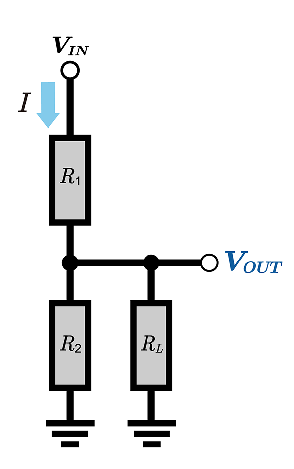
Consider a voltage divider comprising two series resistors, R1 and R2, across an input voltage VIN. With R1 and R2 in series, the current is I. Measuring across R2 gives VOUT =IR2.
\(V_{OUT}=I×R_2\)
Substituting I=VIN /(R1+R2) into this equation yields the following:
\(V_{OUT}=\displaystyle\frac{V_{IN}}{R_1+R_2}×R_2\)
This is the fundamental voltage divider equation. In other words, when R1 and R2 are connected in series, the output voltage VOUT can be viewed as the fraction R2/(R1+R2) of VIN that appears across R2:
\(V_{OUT}=\displaystyle\frac{R_2}{R_1+R_2}V_{IN}\)
Similarly, the voltage across R1 is
\(V_{R_1}=I×R_1=\displaystyle\frac{V_{IN}}{R_1+R_2}×R_1\)

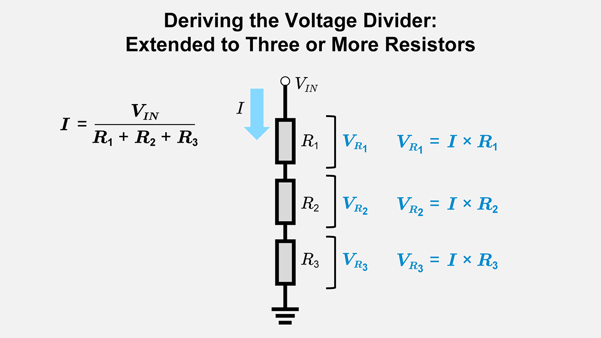
Extending to Three or More Resistors
You can extend the same principle to a series string of multiple resistors. For example, consider R1, R2, …, RN in series. The current I through the series is
\(I=\displaystyle\frac{V_{IN}}{R_1+R_2+⋯+R_N}\)
Since the current is the same through all resistors, each voltage drop is proportional to the corresponding resistor value. This generalizes as follows: the voltage at any tap equals VINRT /(∑RI).
\(V_{OUT}=\displaystyle\frac{R_{T}}{R_1+R_2+⋯+R_N}×V_{IN}\)
\(V_{R_1}=I×R_1, V_{R_2}=I×R_2,⋯\)
where RT is the sum of the resistances from the tap to the reference node (ground), i.e., the “lower-leg” resistance.
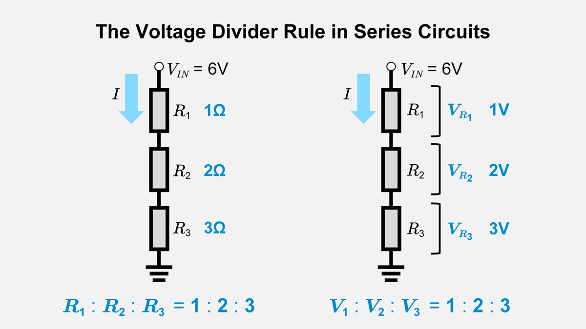
The Voltage Divider Rule
In a series circuit, each resistor’s share of the total voltage is determined by how its resistance compares to the sum of all series resistances. This principle, often called the voltage divider rule, lets you quickly calculate how much input voltage appears across any chosen resistor. It is fundamental to nearly all voltage divider calculations, used to compute the voltage across any element in two- or multi-resistor series networks.
Design Examples and Calculation Procedures
Below are sample design processes illustrating how to choose resistor values step by step. These numerical examples show how a voltage divider’s behavior is determined and how to select values that meet your design targets.
Basic Two-Resistor Divider Example
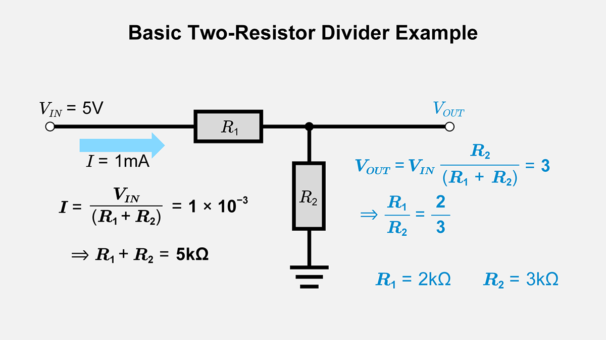
Suppose VIN =5V and you want VOUT =3V. You have two resistors, R1 and R2. The fundamental voltage divider equation becomes
\(V_{OUT}=\displaystyle\frac{V_{IN}}{R_1+R_2}×R_2⟹3=\displaystyle\frac{5}{R_1+R_2}×R_2\)
Rearranging,
\(\displaystyle\frac{R_1}{R_2}=\displaystyle\frac{2}{3}\)
If you need to limit the current to 1mA,
\(I=\displaystyle\frac{V_{IN}}{R_1+R_2}⟹1×10^{−3}=\displaystyle\frac{5}{R_1+R_2}\)
then R1+R2=5kΩ. Matching the 2 : 3 ratio, you might choose R1=2kΩ and R2=3kΩ. In practice, you would pick the closest standard resistor values and consider manufacturing tolerances.
Practical Considerations in Voltage Divider Design
Simply placing two or more resistors in series is not enough. You must consider real-world factors such as load conditions and the presence of other components. This section discusses major design concerns, including load effects, power dissipation, and temperature coefficients, ensuring a stable voltage ratio in actual usage.
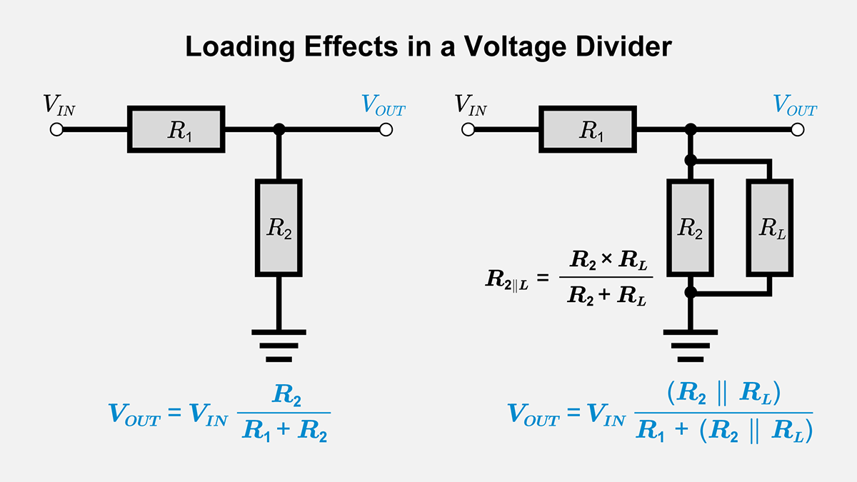
Loading Effect
The “load” refers to whatever circuit or device is connected to the voltage divider’s output node.
If you attach a load resistor RL in parallel with R2, then
\(R_2∥R_{L}=\displaystyle\frac{R_2×R_{L}}{R_2+R_{L}}\)
becomes the effective lower leg of the divider. This can cause the output voltage to drop below the intended level. One standard solution is to buffer the output with a high-input-impedance amplifier or ensure the load has a high resistance.
Accounting for Real-World Load
Consider RL=9kΩ in parallel with R2.
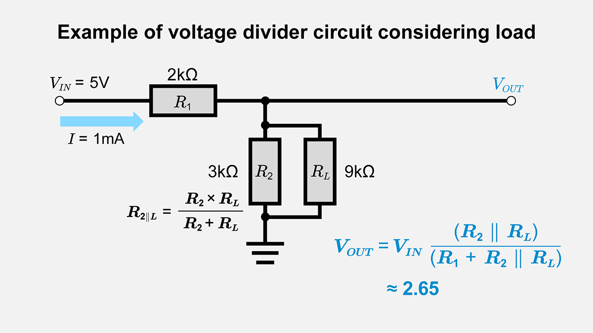
The effective lower leg of the divider is
\(R_2∥R_{L}=\displaystyle\frac{R_2×R_{L}}{R_2+R_{L}}\)
If R2=3kΩ and RL=9kΩ,
\(R_2∥R_{L}=\displaystyle\frac{3k×9k}{3k+9k}=2.25k\)
Then
\(V_{OUT}=\displaystyle\frac{2.25k}{2k+2.25k}×5≈2.65\)
Adding RL in parallel with R2 lowers the effective resistance, so VOUT falls to 2.65 V, below the target 3V.
Consequently, the resistor ratio changes, causing the output voltage to drop. To address this, consider adjusting resistor values or adding an op-amp buffer stage to maintain a stable output voltage.
Varying Load Conditions
The voltage divider output can fluctuate if the load’s resistance changes (for example, in a battery-charging circuit). One approach is to place a buffer amplifier after the divider. Another is to size the divider resistors so that the load current is relatively small, which increases the divider’s current consumption.
Resistor Tolerance
Resistors might have tolerances such as ±5% or ±1%. Even if you design a ratio R1 : R2=7 : 5, actual components values will vary. If you require higher accuracy, using tight-tolerance metal-film resistors or fine-tuning the ratio can help reduce the effect.
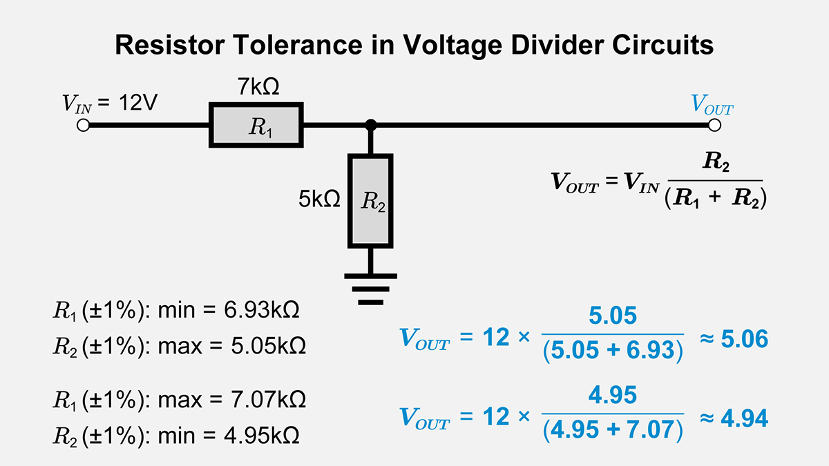
Output‑Voltage Range Due to Tolerance
Assume R1=7.0kΩ ±1% and R2=5.0kΩ ±1%. The input is 12V, and you want 5V out. Each combination of minimum and maximum resistor values yields slightly different results:
\(V_{OUT}=\displaystyle\frac{R_2}{R_1+R_2}×12\)
When R2 is at its highest and R1 at its lowest, you get VOUT (max); the opposite combination gives VOUT (min). This yields an output range centered near 5V. You might choose ±0.1% resistors or add compensation circuitry for tighter precision.
Temperature Factors and Environmental Conditions
Resistor values can shift due to temperature, humidity, or other environmental factors. If a voltage divider is placed in a high-temperature or outdoor environment, select resistors with stable temperature coefficients or shield the circuit. In high-precision applications, temperature compensation or thorough thermal management is crucial.
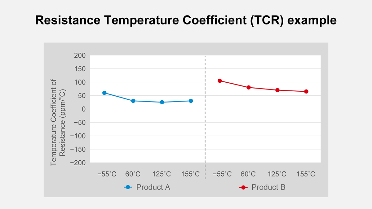
Temperature Coefficient Impact
A resistor’s value shifts with temperature. If a design requires a very stable voltage output, any variation in resistor values can disrupt the voltage ratio. Many resistors are specified by a temperature coefficient (ppm/°C), indicating the fractional or absolute change per °C.
If R1 and R2 have +100ppm/°C, a 10°C rise might yield about 0.1% higher resistance. If both change roughly the same rate, the ratio stays nearly constant, although the absolute resistor values change. Consequently, the output can vary.
You may choose low-TC resistors like metal-film types to achieve reliable performance or maintain a controlled environment.
Power Dissipation and Thermal Issues
Because a voltage divider constantly carries current, its resistors dissipate power. According to Ohm’s law and the relation for electrical power,
\(P=I^2×R\)
or
\(P=\displaystyle\frac{V^2}{R}\)
each resistor in the voltage divider must be rated to handle that power. This is especially relevant for higher-voltage supply lines or circuits carrying significant current. Excessive heat can damage the resistor or alter its resistance characteristics.
Using a Variable Resistor (Potentiometer) as a Voltage Divider
A variable resistor, particularly a potentiometer, contains a movable wiper that adjusts its two internal resistances. This effectively allows you to “tune” the divider ratio. While commonly seen as volume controls in audio, a potentiometer is also a quick way to set or trim voltages in circuit designs.
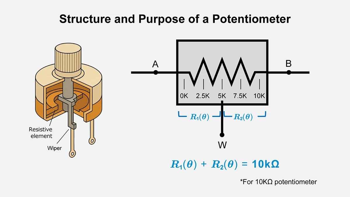
Structure and Purpose of a Potentiometer
A potentiometer has three terminals: two connected to the endpoints of the resistive element and one that moves along it. When the wiper is used with either end terminal, the potentiometer behaves like a variable resistor. A voltage divider is formed in a single package when all three terminals are used.
Terminal Allocation and Resistances
Assume a 10kΩ potentiometer with terminals A (left), W (wiper), and B (right). The total resistance between A and B is always 10kΩ. As the wiper angle θ changes, the resistance from A to W can be represented as R1(θ), and from W to B as R2(θ). These satisfy
\(R_1(θ)+R_2(θ)=10k\)
If the wiper is at 50% rotation, you might have
R1(θ)≈5kΩ, and R2(θ)≈5kΩ
Calculating Potentiometer Divider Voltage
Single-Ended Supply
- Input supply VIN=5V
- 10kΩ potentiometer
- Wiper from 0% to 100%
One end terminal is tied to 5V, the other to ground; the wiper is the output. Ideally, the output varies from 0V (0% rotation) to 5V (100% rotation). At around 30% rotation:
R1≈7kΩ, R2≈3kΩ
\(V_{OUT}=5×0.3=1.5\)
Practical Observations for Volume Controls
An audio amplifier’s volume knob often uses an audio-taper (logarithmic) potentiometer to match human hearing. The principle remains the same: the potentiometer forms a voltage divider with a resistance taper chosen for smooth volume control. If the next stage has a low input impedance, the divider output will vary more than expected, highlighting the need to consider overall impedance design.
Typical Uses of a Voltage Divider
Reviewing typical applications clarifies design trade-offs. Dividers play many roles, from basic biasing to sensor interfaces or voltage monitoring. This section outlines common scenarios where voltage dividers are used.
Biasing in Transistor Circuits
Transistors require a stable bias voltage at the base (or gate) to operate at the desired point.
A pair of resistors, R1 and R2, can form a simple voltage divider to supply a fixed fraction of VCC to the transistor’s base VB:
\(V_{B}=\displaystyle\frac{R_2}{R_1+R_2}×V_{CC}\)
In practice, you must account for base current, transistor gain, and temperature variations. Even so, a simple voltage divider is a foundation for many biasing methods in analog circuits.

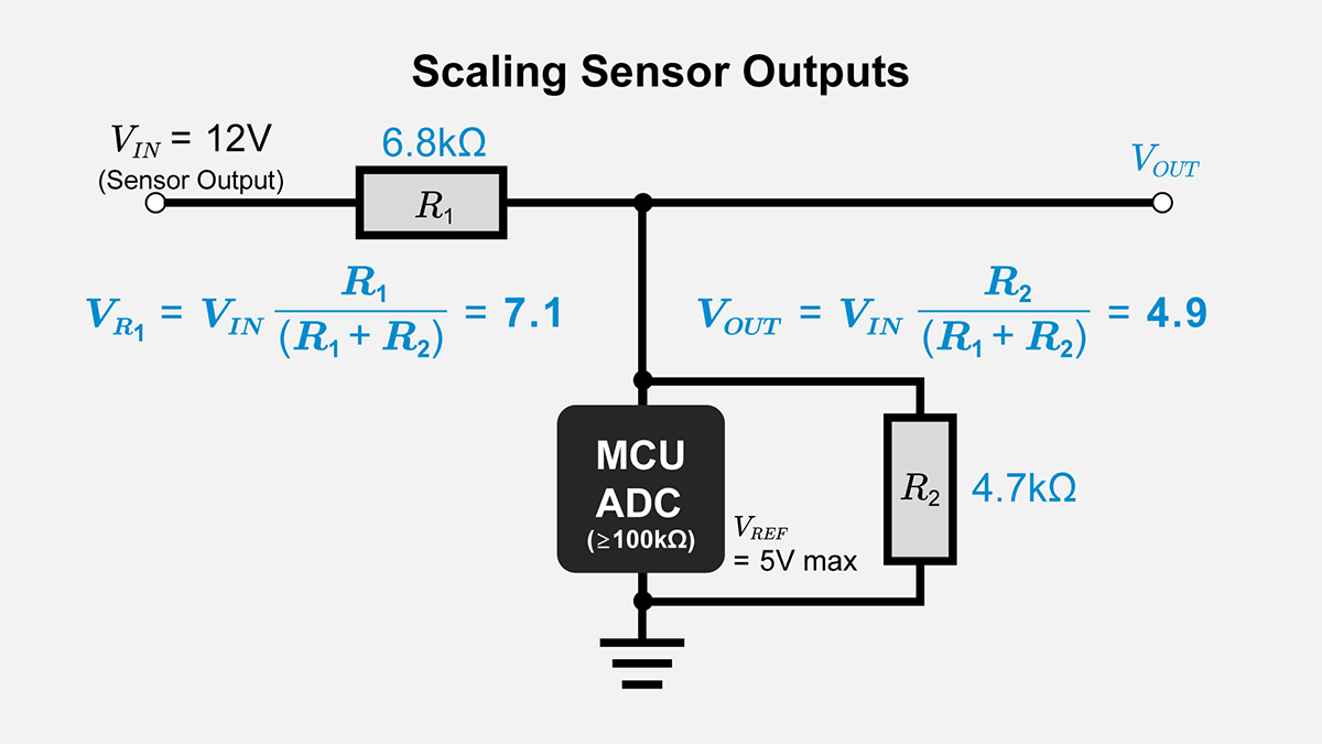
Scaling Sensor Outputs
Some sensors output voltages beyond what a microcontroller’s input can handle. A voltage divider safely scales this to a lower voltage. If a sensor gives up to 12V, but a microcontroller’s ADC limit is 5V, you can select R1 and R2.
\(\displaystyle \frac{R_2}{R_1+R_2}×12=5\)
This way, the sensor signal can be measured without damage to the microcontroller.
Other Applications
Voltage-monitoring or metering circuits
A resistor divider is a quick and straightforward solution for monitoring a 20V power supply and feeding it into an analog-to-digital converter (ADC) that accepts 5V. However, you must consider the accuracy of the divider ratio and the input impedance it presents.
Capacitive Voltage Divider
While most voltage dividers are composed of resistive elements, a capacitive voltage divider can also be created by placing capacitors in series. In this scenario, the voltage drop across each capacitor depends on its reactance at a given frequency. A capacitive voltage divider can be helpful in AC or high-frequency applications where resistive losses are undesirable. However, the division ratio varies with frequency, so designers must ensure that the target signal or supply operates within an appropriate range. Also note that a capacitive voltage divider does not dissipate DC power like a resistive divider. Still, it can introduce other complexities such as load-dependent behavior and potential safety concerns when used at higher voltages.
Combining Voltage Dividers with Other Circuit Elements
A voltage divider is not always used alone. It can become part of more sophisticated designs when paired with operational amplifiers or transistors. This section introduces buffer circuits and feedback loops that incorporate voltage dividers.
Op Amp Buffering and Voltage Dividers
By connecting the output of a voltage divider to the high-input-impedance noninverting input of an op amp configured as a voltage follower (buffer), the input current drawn from the divider becomes extremely small (typically in the range of pA to nA, corresponding to an input resistance of several GΩ). Therefore, the voltage divider sees virtually no load, except for a minimal input bias current and the divider current I=VIN /(R1+R2). This significantly reduces the load’s effect on the divider ratio.
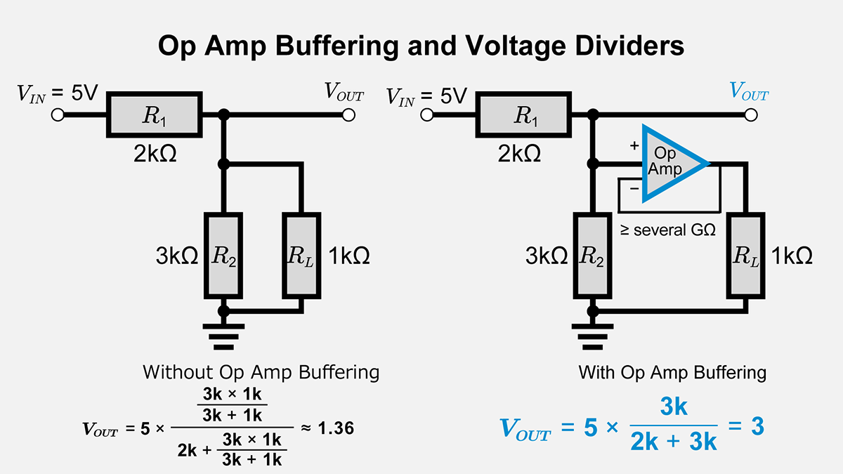
Reducing Load Effects with a Buffer
If R1=2kΩ, R2=3kΩ, VIN=5V, and RL=1kΩ, the unbuffered divider’s output can drop well below 3V. With an op amp in a voltage follower configuration, the load current is provided by the op amp output. The divider only conducts the tiny input bias current, so VOUT remains near 3V.
Feedback Circuits Using Voltage Dividers
Many power supplies or regulators use a voltage divider to sense the output and compare it to an internal reference. For instance, a linear regulator keeping 1.25V at its feedback pin can deliver an adjustable output VOUT set by
\(V_{OUT}=1.25\begin{pmatrix}1+\displaystyle \frac{R_2}{R_1}\end{pmatrix}\)
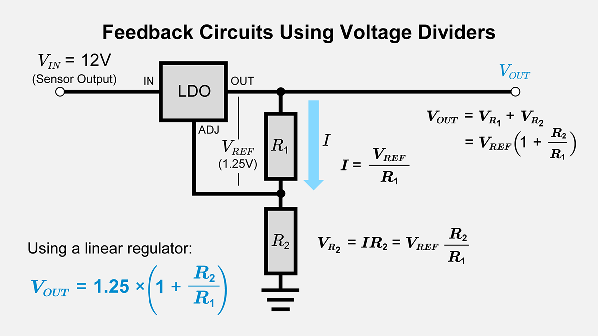
If you want 5V,
\(V_{OUT}=1.25\begin{pmatrix}1+\displaystyle \frac{R_2}{R_1}\end{pmatrix}⟹\displaystyle\frac{R_2}{R_1}=3\)
Hence, R1 : R2=1 : 3 (e.g., 10kΩ and 30kΩ). The voltage divider thus defines the regulated output.
Voltage Dividers in Voltage Regulators
Some linear and switching voltage regulators incorporate an internal or external voltage divider to set their desired output level. In addition to the feedback pin scenario above, certain regulators offer a “sense” pin that reads a fraction of the output voltage through an internal or external divider network. By changing the resistor ratio, you program the regulator’s output voltage effectively. Care must be taken to ensure the divider draws sufficient current to maintain a stable reference, yet not so large as to waste power or destabilize the regulator’s control loop.
Conclusion
A voltage divider is a basic method of splitting an input voltage by a fixed resistor ratio. It finds wide-ranging applications, from biasing transistors to scaling sensor signals and monitoring high-voltage lines. When selecting resistor pairs, designers should account for load, temperature drift, and resistor tolerance. Using a buffer amplifier or feedback mechanism can boost stability and performance. Matching the design to the operating environment and required function ensures a reliable, desired output voltage.
A firm grasp of voltage divider concepts is a cornerstone of electronics design. Even though the principle is straightforward, it has extensive uses. In cases where a simple divider alone is insufficient, additional techniques (op amp buffering, temperature compensation, or isolation measures) can enhance safety and stability. Mastering voltage divider fundamentals gives you a key tool for understanding overall circuit operation and designing solutions for many electronic scenarios.
【Download Documents】 DC Circuit Fundamentals
This handbook summarizes the fundamental laws and circuit analysis methods of DC circuits covered in each article. It outlines derivations and circuit behavior, highlighting essential ideas for circuit design.
Electrical Circuit Design
Basic
- Soldering Techniques and Solder Types
- Seven Tools for Soldering
- Seven Techniques for Printed Circuit Board Reworking
-
Basic Alternating Current (AC)
- AC Circuits: Alternating Current, Waveforms, and Formulas
- Complex Numbers in AC Circuit
- Electrical Reactance
- What is Impedance? AC Circuit Analysis and Design
- Impedance Measurement: How to Choose Methods and Improve Accuracy
- Impedance Matching: Why It Matters for Power Transfer and Signal Reflections
- Resonant Circuits: Resonant Frequency and Q Factor
- RLC Circuit: Series and Parallel, Applied circuits
- What is AC Power? Active Power, Reactive Power, Apparent Power
- Power Factor: Calculation and Efficiency Improvement
- What is PFC?
- Boundary Current Mode (BCM) PFC: Examples of Efficiency Improvement Using Diodes
- Continuous Current Mode (CCM) PFC: Examples of Efficiency Improvement Using Diode
- LED Illumination Circuits:Example of Efficiency Improvement and Noise Reduction Using MOSFETs
- PFC Circuits for Air Conditioners:Example of Efficiency Improvement Using MOSFETs and Diodes
-
Basic Direct Current (DC)
- Ohm’s Law: Voltage, Current, and Resistance
- Electric Current and Voltage in DC Circuits
- Kirchhoff’s Circuit Laws
- What Is Mesh Analysis (Mesh Current Method)?
- What Is Nodal Analysis (Nodal Voltage Analysis)?
- Thevenin’s Theorem: DC Circuit Analysis
- Norton’s Theorem: Equivalent Circuit Analysis
- What Is the Superposition Theorem?
- What Is the Δ–Y Transformation (Y–Δ Transformation)?
- Voltage Divider Circuit
- Current Divider and the Current Divider Rule