Electrical Circuit Design|Basic
Current Divider and the Current Divider Rule
2026.01.20
table of contents
- ・Understanding the Current Divider
- ・Why the Current in a Parallel Circuit Is Inversely Proportional
- ・Using Conductance to Understand Current Division
- ・Practice Problems for Current Divider Circuits
- ・Important Considerations When Designing a Current Divider
- ・Comparing a Current Divider to a Voltage Divider
- ・Troubleshooting and Practical Considerations
- ・Examples of Current Divider Applications
- ・Conclusion
A current divider is a circuit configuration in which the total current is split among multiple parallel branches so that each component or load receives the desired current. You can efficiently control current distribution by configuring parallel resistors (or other parallel combinations). This helps reduce heat buildup and voltage drop throughout your electronic circuits, improving stability and reliability. For instance, you can route most of a large source current through a shunt path so that only a small portion flows through a sensitive meter, ensuring safe operation. Below, we discuss the current divider rule and demonstrate how to perform accurate calculations in various circuit configurations.
Simple Current Divider Calculator
Understanding the Current Divider
A current divider is a parallel network in which the total current splits among branches in inverse proportion to their resistances (or in direct proportion to their conductances). In parallel circuits, all branches share the same voltage. According to Kirchhoff’s current law (KCL), the total current entering a node must equal the sum of the branch currents leaving that node. A current divider (current divider circuit) exploits this principle: current divides among parallel branches in inverse proportion to each branch’s resistance (or in direct proportion to its conductance).

Basic Form of the Current Divider Rule
The current divider rule states that in a set of parallel branches, the current flowing in each particular branch is determined by a straightforward formula. In general, if the total circuit current is It and you want the branch current Ik through the resistor Rk (the parallel equivalent is Rt), use:
\(I_{k}=I_{t}×\displaystyle\frac{R_{t}}{R_{k}}\)
Notation used throughout: It (total current), Rt (equivalent resistance of the parallel network), Ik and Rk (branch current and resistance).
Although the formula is written as the ratio Rt /Rk, it actually expresses an inverse relationship: branches with smaller resistance carry a large share of the total current. The following section shows how this formula arises in detail.
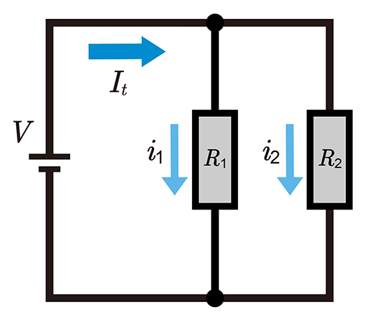
Step-by-Step Derivation with Two Resistors
- Assumptions: Suppose two resistors R1 and R2 form a parallel configuration. Let the supply voltage be V, the total current be It, and the equivalent resistance be Rt.
Calculate the Equivalent Resistance

In parallel,
\(\displaystyle\frac{1}{R_{t}}=\displaystyle\frac{1}{R_1}+\displaystyle\frac{1}{R_2}⟹R_{t}=\displaystyle\frac{R_1×R_2}{R_1+R_2}\)
Apply Ohm’s Law to Each Branch
\(i_1=\displaystyle\frac{V}{R_1}, i_2=\displaystyle\frac{V}{R_2}\)
Relate the Equivalent Resistance to the Total Current
\(I_{t}=i_1+i_2=\displaystyle\frac{V}{R_1}+\displaystyle\frac{V}{R_2}=\displaystyle\frac{V}{R_{t}}\)
Express the Branch Current as a Ratio
Taking the ratio of the branch current to the total current gives
\(\displaystyle\frac{i_1}{I_{t}}=\displaystyle\frac{\displaystyle\frac{V}{R_1}}{\displaystyle\frac{V}{R_{t}}}=\displaystyle\frac{R_{t}}{R_1}\)
so
\(i_1=I_{t}×\displaystyle\frac{R_{t}}{R_1}\)
In the same way,
\(i_2=I_{t}×\displaystyle\frac{R_{t}}{R_2}\)
Thus, we confirm the basic principle behind the current divider rule: branches with lower resistance draw a larger portion of the total current in a parallel circuit.
Why the Current in a Parallel Circuit Is Inversely Proportional
When dealing with parallel circuits, each branch sees the same voltage. By Ohm’s law, I=V /R. Hence, if a branch’s resistance is small, the branch current is large. This direct outcome is the foundation of the current divider concept. For instance, if R1 < R2, then i1 > i2, and i1+i2=It.
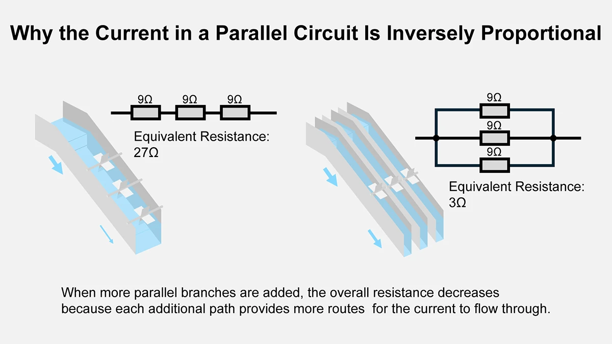
Reduction of Equivalent Resistance
When more parallel branches are added, the overall resistance decreases because each additional path gives the current more ways to flow. This reduced equivalent resistance is beneficial in specific electronic circuits that handle large currents, letting the system operate more efficiently while balancing current among various branches.
Using Conductance to Understand Current Division
Some engineers prefer to handle current divider calculations using the reciprocal of resistance, known as conductance. This approach can simplify complex circuits with multiple parallel resistors.
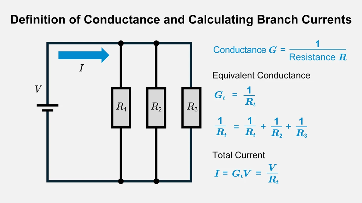
Definition of Conductance
Conductance G is defined as 1/R. Thus, a smaller R implies a larger G. The total conductance in a parallel combination is simply the sum of the individual conductances:
\(G=\displaystyle\frac{1}{R}\)
\(I_{t}=V×G_{t}\) (\(G_{t}=G_1+G_2+…+G_{n}\))
Calculating Branch Currents Using Conductance
If the parallel network experiences the same input voltage V, then the current ik in the k-th branch with conductance Gk is:
\(i_{k}=V×G_{k}=\displaystyle\frac{G_{k}}{G_{t}}I_{t}\)
Hence, the total circuit current is V multiplied by the sum of all conductances Gt.
Conductance Simplifies Complex Circuits
For circuits with multiple branches, summing conductances often proves more convenient than dealing with numerous inverses of R. This is particularly helpful in unevenly loaded or otherwise complex circuits where each branch might have a different value.
Simulation Tools
Commercial and open-source circuit simulators (like a SPICE-based tool) allow accurate calculations of branch currents under assumed polarities, including stray or parasitic elements not shown in the simplified schematic. Combining theoretical analysis with simulation fosters more precise calculations of the current distribution.
Practice Problems for Current Divider Circuits
Here, we introduce concrete examples of calculating current in parallel branches. By substituting numeric values, you can see how the current divider rule works in basic current divider circuits.
Example with Two Resistances in Parallel
- supply voltage V=12V
- resistor R1=6Ω
- resistor R2=3Ω

- Determine the Equivalent Resistance
\(\displaystyle\frac{1}{R_{t}}=\displaystyle\frac{1}{R_1}+\displaystyle\frac{1}{R_2}=0.5\)
So,
\(R_{t}=\displaystyle\frac{1}{0.5}=2\)
- Determine Total Circuit Current
\(I_{t}=\displaystyle\frac{12}{2}=6\) - Determine Individual Branch Currents
- resistor R1 (6Ω): i1=12/6=2A
- resistor R2 (3Ω): i2=12/3=4A
They sum to 6A, matching the total circuit current.
Example with Three Resistances in Parallel
- supply voltage V=12V
- resistor R1=4Ω
- resistor R2=6Ω
- resistor R3=12Ω

- Equivalent Resistance
\(\displaystyle\frac{1}{R_{t}}=\displaystyle\frac{1}{4}+\displaystyle\frac{1}{6}+\displaystyle\frac{1}{12}=0.5\)
Hence,
\(R_{t}=\displaystyle\frac{1}{0.5}=2\)
- Total Current
\(I_{t}=\displaystyle\frac{12}{2}=6\) - Branch Currents
- R1 (4Ω): i1=12/4=3A
- R2 (6Ω): i2=12/6=2A
- R3 (12Ω): i3=12/12=1A
Summation: 3+2+1=6A.
- Power Dissipation
\(P=i^2×R\)Use P=I2×R to find the power of each resistor:
- R1 (4Ω): P1=32×4=36W
- R2 (6Ω): P2=22×6=24W
- R3 (12Ω): P3=12×12=12W
Total 36+24+12=72W, which matches (6A)2x2Ω=72W.
Important Considerations When Designing a Current Divider
Even if you understand how a current divider formula works, you can still face various practical challenges. Below are some real-world factors that must be addressed in electrical circuits involving parallel branches.
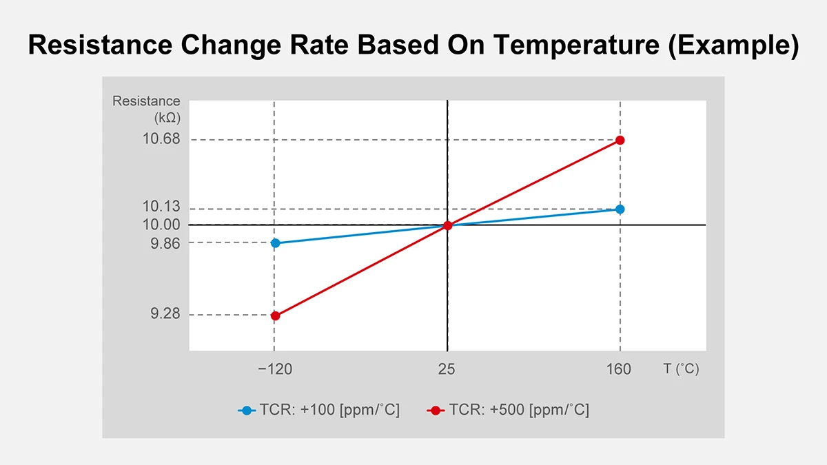
Resistor Tolerances and Temperature Effects
Many real resistors have tolerance ranges (e.g., ±5% or ±10%) and temperature coefficients that shift their nominal values. In high-current parallel circuits, the actual current distribution can deviate from the theoretical calculation because the resistor heating changes its practical value. The design should therefore include adequate margin for each branch and verify that no resistor is operated beyond its safe limits.
Reference: TCR (Temperature Coefficient of Resistance) Calculation Tool from ROHM
Comparing Power with Rated Values
If each resistor in your design must handle at most 10W, the 36W on resistor 1 means it will exceed the rating. That indicates a risk of damage or a short circuit in practice. Hence, choose a 50W resistor for R1 or incorporate extra heat dissipation. You could also change the resistor ratio to reduce that branch’s current.
Wiring and Contact Resistance
In real boards or electronic circuits, solder joints, connectors, or the PCB can add small extra resistances. Even a minor contact resistance can lead to uneven current distribution or local heating in high-current designs. If your measurements differ from theoretical results, check for such hidden resistances.
Meter and Sensor Internal Resistance
Measuring branch currents with a sensor or meter can also alter the current ratio. A sensor inserted in the circuit will introduce some series or parallel impedance. For accurate calculations, consider or measure this extra factor so it does not create a hidden error in your current divider design.
Comparing a Current Divider to a Voltage Divider
Whereas a current divider controls how current divides among parallel branches, a voltage divider (voltage divider rule) uses a series connection to split an input voltage. In a voltage divider, the voltage is distributed proportionally to resistor ratios in series. This differs from the current divider’s inverse proportion relationship in parallel resistors.

Basic Voltage Divider Formula
When you have two resistors, R1 and R2, in series with a supply voltage, the fraction of voltage across R1 is:
\(V_1=V×\displaystyle\frac{R_1}{R_1+R_2}\)
In short, series networks divide voltage in direct proportion to resistance, whereas parallel networks divide current in inverse proportion to resistance. One formula divides voltage in a series, while the other divides current in a parallel arrangement.
When to Use a Current Divider vs. a Voltage Divider
Consider a current divider when splitting current among multiple resistors or loads in parallel. By contrast, you use a voltage divider if you want different output voltages from the same source in a series chain.
Troubleshooting and Practical Considerations
Various issues may arise if the theoretical and measured results do not match when implementing a current divider in real electronic circuits.
Unexpected Current Paths
Traces or components might create unplanned parallel pathways on large or complicated boards. If the sum of measured currents does not align with predictions, look for a short circuit or stray conduction path.
Nonlinear Components and Operating Conditions
At high temperatures or large currents, resistors can deviate from ohmic behavior. Small chip resistors may have a strong temperature coefficient. If semiconductors are present, the circuit is no longer a pure resistor network, and a more detailed analysis is needed.
Behavior at High Frequencies
At higher frequencies, the equivalent impedance includes inductive or capacitive reactances. Calculations that assume purely resistive elements may break down, making a simple current divider formula less valid. Instead, advanced methods or simulation tools help ensure accurate analysis in complex circuits.
Examples of Current Divider Applications
A current divider can be used in many electrical engineering contexts. Below are some typical uses:
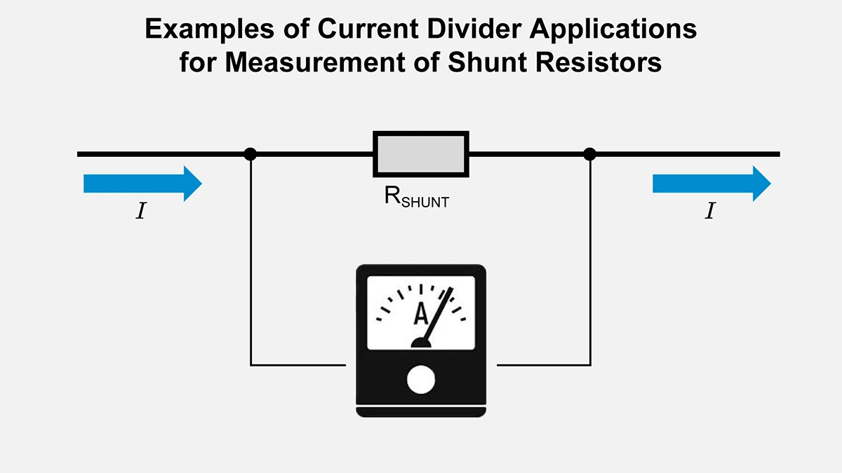
Shunt Resistors for Measurement
Specific ammeter circuits measure large currents by placing a low-value shunt resistor in parallel with a sensitive meter movement. Most of the total current flows through the low-value shunt resistor, while only a small fraction flows through the meter. By measuring the small current in the meter or the corresponding voltage drop across the shunt, the circuit can infer the total current. This arrangement is a direct application of the current divider principle.
Protecting Sensitive Devices
Some sensors or measurement devices can only tolerate a small current. The remainder of the current divides into another parallel path with a lower resistance, ensuring the protected device never experiences more current than it can handle.
Parallel Regulators and Power Splitting
Power electronics may need to distribute a large supply current across multiple parallel regulators or branches. By configuring the branches carefully, each output current can be maintained safely, avoiding uneven loading or excessive thermal stress.
Conclusion
A current divider circuit (current divider) and the current divider rule are fundamental for understanding how current divides in parallel branches within electronic circuits. Even though each branch experiences the same voltage, differences in the individual resistances lead to an inverse current distribution among the parallel resistors. By accurately determining total current, branch currents, and power dissipation, you can design safe and reliable systems for a wide range of electrical and electronic applications.
Beyond theory, practical designs require considering resistor tolerances, temperature effects, wiring resistances, and more. Combining theoretical calculations with measurements or simulations will yield more precise and reliable results. Mastering the principles of the current divider expands your ability to handle complex circuits, from basic circuit configurations to large-scale electrical systems.
【Download Documents】 DC Circuit Fundamentals
This handbook summarizes the fundamental laws and circuit analysis methods of DC circuits covered in each article. It outlines derivations and circuit behavior, highlighting essential ideas for circuit design.
Electrical Circuit Design
Basic
- Soldering Techniques and Solder Types
- Seven Tools for Soldering
- Seven Techniques for Printed Circuit Board Reworking
-
AC Circuits Fundamentals: Article Guide
- AC Circuits: Alternating Current, Waveforms, and Formulas
- Complex Numbers in AC Circuit
- Fundamentals of Capacitive Circuits: Understanding Series and Parallel Capacitor Connections
- Electrical Reactance
- What is Impedance? AC Circuit Analysis and Design
- Impedance Measurement: How to Choose Methods and Improve Accuracy
- Impedance Matching: Why It Matters for Power Transfer and Signal Reflections
- Resonant Circuits: Resonant Frequency and Q Factor
- RLC Circuit: Series and Parallel, Applied circuits
- What is AC Power? Active Power, Reactive Power, Apparent Power
- Power Factor: Calculation and Efficiency Improvement
- What is PFC?
- Boundary Current Mode (BCM) PFC: Examples of Efficiency Improvement Using Diodes
- Continuous Current Mode (CCM) PFC: Examples of Efficiency Improvement Using Diode
- LED Illumination Circuits:Example of Efficiency Improvement and Noise Reduction Using MOSFETs
- PFC Circuits for Air Conditioners:Example of Efficiency Improvement Using MOSFETs and Diodes
-
DC Circuits Fundamentals: Article Guide
- Ohm’s Law: Voltage, Current, and Resistance
- Electric Current and Voltage in DC Circuits
- Kirchhoff’s Circuit Laws
- What Is Mesh Analysis (Mesh Current Method)?
- What Is Nodal Analysis (Nodal Voltage Analysis)?
- Thevenin’s Theorem: DC Circuit Analysis
- Norton’s Theorem: Equivalent Circuit Analysis
- What Is the Superposition Theorem?
- What Is the Δ–Y Transformation (Y–Δ Transformation)?
- Voltage Divider Circuit
- Current Divider and the Current Divider Rule