
Electrical Circuit Design|Basic
Fundamentals of Capacitive Circuits: Understanding Series and Parallel Capacitor Connections
2026.07.06
table of contents
- ・Fundamentals of Capacitive Circuits
- ・Series and Parallel Capacitor Connections and Equivalent Capacitance
- ・Analyzing Capacitive Circuits in DC
- ・Capacitive Circuits in AC: Charging, Phase Angle, and Waveforms
- ・Understanding Capacitive Reactance in AC Circuits
- ・Power and Energy in AC Capacitor Circuits
- ・Design Considerations for Real-World AC Capacitor Circuits
- ・Summary: Making the Most of Capacitive Circuits
Capacitive circuits are a broad category of circuits that exploit the way a capacitor temporarily stores electric charge (and energy) in an electric field. By placing capacitors appropriately, engineers can smooth power-supply ripple, shunt high-frequency noise to ground, or block DC while coupling only the AC (signal) component. In real designs, it is common to combine multiple capacitors in series and/or parallel to meet required capacitance, voltage rating, and high-frequency performance, and then treat the combination as an equivalent capacitance. Becoming comfortable with the concept of equivalent capacitance is often the first key step in understanding capacitive circuits. This article starts with series and parallel combinations, then moves on to RC transient response and capacitive reactance, and finally summarizes practical design considerations.
Fundamentals of Capacitive Circuits
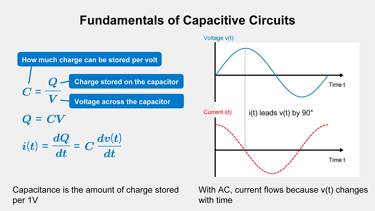
A capacitor is the central component in a capacitive circuit. Physically, it consists of two conductors separated by a dielectric; charge separation on the plates establishes an electric field between its terminals. In circuit diagrams, a capacitor is represented by two parallel plates. By examining capacitor behavior across frequencies (from low to high), you can understand why capacitors are widely used for filtering, signal coupling, energy buffering, and power-supply stabilization. A practical rule is that an ideal capacitor blocks steady-state DC (after transients settle) but allows current to flow whenever its voltage changes with time. In circuit analysis, this is modeled as current entering or leaving the capacitor terminals, even though the underlying mechanism is charge movement on the plates and displacement current through the dielectric.
Mathematical Model, Capacitor Voltage, and Capacitance Units
Capacitance is often defined as the amount of charge stored per unit voltage. Written formally, for an ideal capacitor:
\(C=\displaystyle\frac{Q}{V}\)
Here, Q is the charge stored on the capacitor plates, and vc is the voltage across the capacitor terminals (the capacitor voltage). Therefore, Q=C·vc . For time-varying signals, you may write Q(t)=C·vc(t). In the discussion below, we will use VDC for a DC supply voltage, vs(t) for a time-varying source (typically AC), and vc(t) for the capacitor voltage. When the voltage changes with time, the stored charge also changes, and that change appears as current flowing into or out of the capacitor terminals. The SI unit of capacitance is the farad (F), where 1 F = 1 C/V. Because 1 F is very large for most electronics, practical designs commonly use values in microfarads (µF), nanofarads (nF), or picofarads (pF), depending on the application.
Series and Parallel Capacitor Connections and Equivalent Capacitance
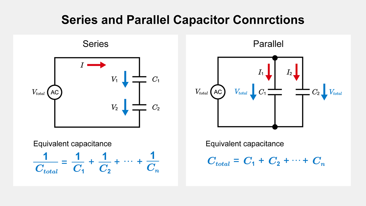
In practical circuits, you rarely use only a single capacitor. Multiple capacitors are often combined to achieve a target capacitance, increase the effective voltage rating, or shape frequency behavior by mixing capacitor technologies. These combinations are analyzed by replacing the network with an equivalent capacitance Ctotal.
Series Connection
When capacitors are connected in series, the equivalent capacitance Ctotal becomes smaller than any individual capacitor in the chain. It is computed as:
\(\displaystyle\frac{1}{C_{total}}=\displaystyle\frac{1}{C_1}+\displaystyle\frac{1}{C_2}+⋯+\displaystyle\frac{1}{C_n}\)
Because the same charge Q must appear on each series capacitor, the voltage across each capacitor is Vi =Q / Ci. This means the device with the smallest capacitance tends to see the largest share of the total voltage. Series stacks are therefore sometimes used to achieve a higher overall voltage rating, but in real designs you must be mindful of capacitance tolerance and leakage-current mismatch. To prevent a single capacitor from being overstressed, designers may add balancing resistors (voltage-equalizing resistors) across each capacitor to control the DC voltage division.
Parallel Connection
When capacitors are connected in parallel, the equivalent capacitance is simply the sum of the individual capacitances:
\(C_{total}=C_1+C_2+⋯+C_n\)
Parallel combinations are used when a larger total capacitance is required or when different capacitor types are combined to take advantage of complementary characteristics. For example, a small ceramic capacitor can provide low impedance at high frequency, while a larger electrolytic or polymer capacitor can provide bulk energy storage at lower frequencies. In a parallel network, each capacitor sees the same applied voltage because their terminals share common nodes.
From this point onward, the symbol C may refer either to a single capacitor or to an equivalent capacitance Ctotal obtained from a series/parallel network. When multiple capacitors are combined, substitute the appropriate Ctotal for C. In those cases, vc(t) refers to the voltage across the entire capacitor network.
Analyzing Capacitive Circuits in DC
Charging a Capacitor from a DC Source
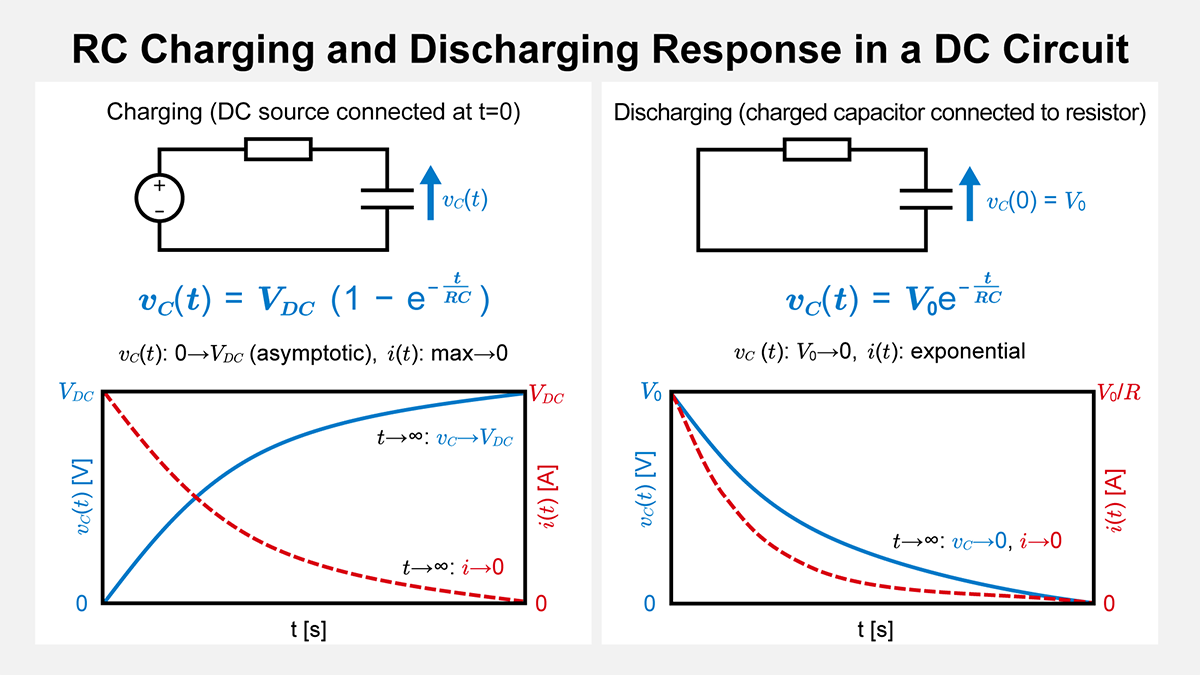
When a capacitor is connected to a DC source, a charging transient occurs. If the capacitor voltage starts at 0 V, the difference between the source voltage and the capacitor voltage is initially at its maximum, so a large current can flow (limited by any series resistance R). As charge accumulates and the capacitor voltage vc(t) rises, the voltage difference decreases and the current decays. The terminal current of an ideal capacitor is related to the capacitor voltage by:
\(i(t)=C\displaystyle\frac{dv_c(t)}{dt}\)
In this article, vc(t) is defined as the potential at the positive terminal minus the potential at the negative terminal. The current i(t) is defined as positive when it flows into the positive terminal (the passive sign convention). In steady state under DC (after sufficient time), dvc(t) / dt → 0, so i(t) → 0 and the capacitor behaves like an open circuit.
Deriving the Exponential RC Charging Response
Consider the basic RC charging circuit in which a resistor R and a capacitor C are connected in series and driven by a DC source VDC. A standard derivation proceeds as follows.
- Apply Kirchhoff’s voltage law: the resistor drop i(t)·R plus the capacitor voltage vc(t) equals the source voltage VDC.
- Substitute i(t) = C·dvc(t) / dt to obtain a first-order differential equation.
- Solve the first-order linear differential equation for vc(t).
The resulting capacitor voltage is:
\(v_{c}(t)=V_{DC}(1-e^{-\frac{t}{RC}})\)
At t = 0, vc(0) = 0 (the capacitor is initially uncharged). As time increases, the exponential term e–t/(RC) decays toward zero and vc(t) approaches VDC. After several time constants (RC), the circuit is effectively in steady state and the capacitor blocks DC current, which is one reason capacitors are commonly described as “blocking DC.”
Discharging a Capacitor into a Resistive Load
The reverse transient occurs when a capacitor initially charged to V0 is connected across a resistor R. The capacitor voltage vc(t) decreases exponentially as the stored energy is released through the resistor:
\(v_{c}(t)=V_{0} e^{-\frac{t}{RC}}\)
Here, vc(0) = V0 at t = 0, and the voltage asymptotically approaches 0 V as time progresses. The current magnitude also decays exponentially. Under the passive sign convention defined above, dvc(t) / dt < 0 during discharge, so i(t) = C·dvc(t) / dt becomes negative. If you prefer to treat the discharge current direction as positive, you can reverse the current reference direction accordingly.
Common Applications of Capacitors in DC Circuits
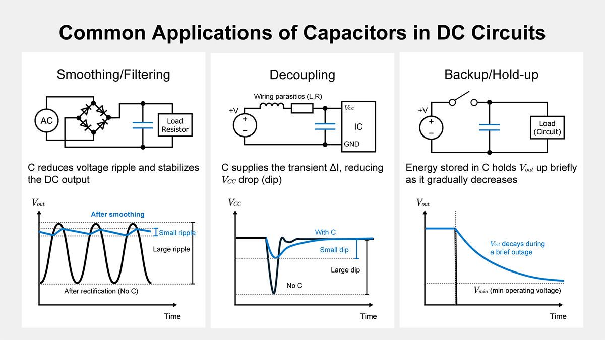
Even in DC systems, capacitors are used in several standard ways.
- Smoothing and filtering
In power supplies, a capacitor placed after a rectifier reduces ripple voltage and helps produce a more stable DC output. - Decoupling (bypass)
In digital and mixed-signal circuits, local decoupling capacitors supply transient current during switching events and suppress voltage dips and noise on the power rails. - Hold-up and backup energy storage
Large-value capacitors can provide short-duration energy during brief supply interruptions or during power sequencing transitions.
Capacitive Circuits in AC: Charging, Phase Angle, and Waveforms
With the DC transient behavior as a foundation, we can now examine what happens when an AC voltage is applied. In AC circuits, the voltage and current are time-varying (often sinusoidal), and the capacitor continuously charges and discharges each cycle.
Charge Reversal and Continuous Cycling in AC Capacitor Circuits
If the source voltage is vs(t) = Vm sin(ωt), the polarity reverses every half cycle. The capacitor is driven to charge in one direction, then to discharge and recharge in the opposite direction. Because a capacitor conducts only when its terminal voltage is changing, the current depends strongly on the rate of change of the voltage. At higher frequencies, dv / dt is larger, so the capacitor current tends to increase. This frequency-dependent behavior is captured more formally by capacitive reactance, discussed later.
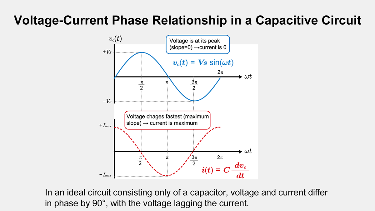
Phase Relationship Between Voltage and Current in a Capacitive Circuit
A key hallmark of an ideal (purely capacitive) circuit is the phase relationship between voltage and current. In an ideal capacitor, the current leads the voltage by 90 degrees. This follows directly from i(t) = C·dvc(t) / dt: when the magnitude of dvc(t) / dt is at its maximum, the current reaches its peak, and when the voltage reaches its maximum or minimum value, dvc(t) / dt = 0 and the current is zero at that instant.
Understanding Capacitive Reactance in AC Circuits
In AC circuits, resistors are not the only elements that oppose current flow. Inductors and capacitors introduce reactance, an opposition that depends on frequency. For a capacitor, this frequency-dependent opposition is called capacitive reactance XC, and it decreases as frequency increases. For additional background on reactance in general, see the related article on reactance.
Reactance Formula and Derivation Steps
Starting from the capacitor relation i(t) = C·dvs(t) / dt and assuming the capacitor voltage is sinusoidal, vs(t) = Vm sin(ωt), we can derive the standard reactance formula.
- Differentiate vs(t) = Vm sin(ωt) to obtain dvs(t) / dt = ω Vm cos(ωt).
- Substitute into i(t) = C ω Vm cos(ωt).
- Define XC as the ratio of voltage amplitude to current amplitude. This yields XC = 1/(ωC).
In the phasor domain, the complex impedance of an ideal capacitor is ZC = 1/(jωC) = -jXC, where j is the imaginary unit. Because ω is the angular frequency (ω = 2πf), the reactance can also be written in terms of frequency f as:
\(X_{C}=\displaystyle\frac{1}{2πf C}\)
XC is measured in ohms (Ω). Note that reactance is not a resistive loss mechanism: an ideal capacitor does not dissipate real power, even though it can carry significant AC current.
Power and Energy in AC Capacitor Circuits
An ideal capacitor does not dissipate real power; over one AC cycle, the net energy delivered to it is zero, although instantaneous power can be positive or negative. In real circuits, energy is exchanged between the source and the capacitor each cycle, and reactive current can lead to additional losses due to wiring resistance and the capacitor’s ESR. Understanding this behavior is important for power factor correction and for robust power and signal integrity design.
Energy Storage and Return in an AC Capacitor
In AC operation, a capacitor repeatedly stores energy as its voltage rises and returns energy as its voltage falls or reverses polarity. The instantaneous energy stored in an ideal capacitor is:
\(\displaystyle E=\displaystyle\frac{1}{2}C\left[v_{c}(t)\right]^2\)
Because vc(t) varies with time (for example, vc(t) = Vm sin(ωt)), the stored energy also varies. Over a full cycle, an ideal capacitor returns the energy it stored, so the average real power is zero. However, the back-and-forth energy flow corresponds to reactive power. If the circuit has resistance (wiring resistance, ESR, etc.), the associated reactive current can still produce I2R losses.
Instantaneous Power and What It Means
The instantaneous power associated with the capacitor is defined as:
\(p(t)=v_{c}(t)\times i(t)\)
For an ideal capacitor, the current is related to the capacitor voltage by:
\(i(t)=C\displaystyle\frac{dv_{c}(t)}{dt}\)
If we assume vc(t) = Vm sin(ωt), then i(t) = C ω Vm cos(ωt), and the instantaneous power becomes:
\(p(t)=\left[V_{m} \sin(ωt)\right]×\left[C ω V_{m} \cos(ωt)\right]=C ω V_{m}^2 \sin(ωt) \cos(ωt)\)
Using the trigonometric identity sin(α)cos(α) = ½ sin(2α), we obtain:
\(p(t)=\displaystyle\frac{C ω V_{m}^2}{2}\ \sin(2ωt)\)
This expression alternates in sign, indicating that energy flows into the capacitor during part of the cycle and flows back out during the other part. For an ideal capacitor, the average over a full cycle is zero.
Energy Exchange and Frequency Dependence
Because XC = 1/(ωC) decreases with increasing frequency, the magnitude of a capacitor’s impedance decreases with frequency, allowing a larger AC current for the same voltage amplitude. This is why capacitors are effective at bypassing high-frequency noise and why they are fundamental to AC coupling and filtering. At the same time, larger capacitance means more charge is exchanged per cycle. In high-current or high-frequency conditions, that reactive current can produce voltage drops across interconnect resistance and generate heat in the capacitor’s ESR, which must be accounted for in design.
Practical Points (Design and Applications)
- Power factor correction: capacitors supply leading reactive power (capacitive VARs), which can offset the lagging reactive power of inductive loads, thereby improving overall power factor.
- Filtering and resonance: together with inductors, capacitors form LC networks that can pass or reject specific frequency bands and create resonant circuits.
- Real-world limitations: practical capacitors have ESR and ESL, and their impedance is not purely capacitive across all frequencies. Ripple-current rating, self-resonant frequency, and thermal constraints become critical in high-current or high-frequency designs.
These characteristics of storing and returning energy under AC make capacitors essential in both electronics and power engineering, from noise suppression and timing networks to reactive power control.
Design Considerations for Real-World AC Capacitor Circuits
When incorporating capacitors into a design, engineers must evaluate performance, reliability, and safety constraints. These considerations apply to simple single-capacitor circuits as well as complex AC capacitor networks.
Thermal Stress and Aging
Capacitors can degrade over time, especially electrolytic capacitors whose characteristics depend on chemical processes. Elevated temperature accelerates aging, often reducing capacitance and increasing ESR. If a capacitor can no longer maintain its intended capacitance, power-supply ripple may increase, filter characteristics may shift, and timing constants may drift. For long-life designs, temperature rating, ripple-current rating, and lifetime specifications must be considered, along with appropriate derating.
PCB Layout and Parasitics
At high frequencies, capacitor leads, packages, vias, and PCB traces introduce parasitic inductance and resistance. These parasitics can change the impedance-versus-frequency characteristic and shift the capacitor’s self-resonant frequency, reducing decoupling effectiveness. To minimize these effects, keep current loops short, place decoupling capacitors close to the load, and consider using multiple capacitors of different values and technologies in parallel to achieve low impedance across a wide frequency range. Good layout also reduces unwanted voltage drop and localized heating associated with high transient currents.
Summary: Making the Most of Capacitive Circuits
Capacitive circuits behave very differently from purely resistive circuits because a capacitor temporarily stores and returns energy rather than dissipating it. By understanding this behavior, engineers can build a wide variety of practical functions, including filtering, timing networks, signal coupling, ripple reduction, decoupling, and power factor correction.
Key foundations include equivalent capacitance for series and parallel connections, exponential charging and discharging in RC networks under DC excitation, the 90-degree phase lead of current in an ideal capacitor under AC excitation, and the frequency-dependent capacitive reactance. In real designs, capacitor selection and placement must also account for ESR, ESL, temperature, aging, and layout-induced parasitics.
By validating designs with simulation, prototype measurements, and appropriate derating, you can select capacitance values, technologies, and mounting practices that achieve both performance and reliability. From simple decoupling networks to advanced reactive power compensation, the underlying principle is the same: manage the relationship between voltage and current by controlling how energy is stored and exchanged in the electric field.
Related Articles
Electrical Reactance
What is AC Power? Active Power, Reactive Power, Apparent Power
Power Factor: Calculation and Efficiency Improvement
【Download Documents】 AC Circuit Fundamentals
This handbook summarizes key AC circuit concepts from each article, including reactance, impedance, resonance, power, and power factor. It outlines derivations and circuit behavior, highlighting essential ideas for circuit design.

Electrical Circuit Design
Basic
- Soldering Techniques and Solder Types
- Seven Tools for Soldering
- Seven Techniques for Printed Circuit Board Reworking
-
AC Circuits Fundamentals: Article Guide
- AC Circuits: Alternating Current, Waveforms, and Formulas
- Complex Numbers in AC Circuit
- Fundamentals of Capacitive Circuits: Understanding Series and Parallel Capacitor Connections
- Electrical Reactance
- What is Impedance? AC Circuit Analysis and Design
- Impedance Measurement: How to Choose Methods and Improve Accuracy
- Impedance Matching: Why It Matters for Power Transfer and Signal Reflections
- Resonant Circuits: Resonant Frequency and Q Factor
- RLC Circuit: Series and Parallel, Applied circuits
- What is AC Power? Active Power, Reactive Power, Apparent Power
- Power Factor: Calculation and Efficiency Improvement
- What is PFC?
- Boundary Current Mode (BCM) PFC: Examples of Efficiency Improvement Using Diodes
- Continuous Current Mode (CCM) PFC: Examples of Efficiency Improvement Using Diode
- LED Illumination Circuits:Example of Efficiency Improvement and Noise Reduction Using MOSFETs
- PFC Circuits for Air Conditioners:Example of Efficiency Improvement Using MOSFETs and Diodes
-
DC Circuits Fundamentals: Article Guide
- Ohm’s Law: Voltage, Current, and Resistance
- Electric Current and Voltage in DC Circuits
- Ohm’s Law: Voltage, Current, and Resistance
- Kirchhoff’s Circuit Laws
- What Is Mesh Analysis (Mesh Current Method)?
- What Is Nodal Analysis (Nodal Voltage Analysis)?
- Thevenin’s Theorem: DC Circuit Analysis
- Norton’s Theorem: Equivalent Circuit Analysis
- What Is the Superposition Theorem?
- What Is the Δ–Y Transformation (Y–Δ Transformation)?
- Voltage Divider Circuit
- Current Divider and the Current Divider Rule