
Electrical Circuit Design|Basic
Series Circuit Calculator for Resistance, Current, Voltage Drop, and Power
2026.10.19
A series circuit has a single current path, so the same current flows through every resistor. Enter the source voltage and resistor values to calculate total resistance, circuit current, each resistor’s voltage drop, and power dissipation.
This guide also explains how to identify series-connected components, derive the formulas, verify the voltage and power totals, and distinguish a series circuit from a parallel circuit.
Series Circuit Calculator
Enter the source voltage and resistor values to calculate total resistance, loop current, the voltage drop across each resistor, and resistor power dissipation. This calculator is intended for steady-state DC circuits containing ideal resistors in series.
Loading the calculator.
The same current flows through every resistor in the series string. The results should also show that the sum of the resistor voltage drops equals the source voltage and that the total resistor power dissipation equals the power supplied by the source. The derivation and calculation steps are explained in “How to Calculate a Series Circuit“.
The results assume nominal input values and ignore wiring resistance and source internal resistance. For a real design, include source-voltage tolerance, resistor tolerance, and temperature effects.
How to Identify a Series Connection
To identify a series-connected section in a schematic, examine the node shared by adjacent components and check whether any other branch leaves that node. This separates the components that carry the same current from sections where current divides.
Two Components Are in Series When the Shared Node Has No Branch
Two-terminal components are in series when they share a node and no other branch leaves that node. A node consists of points connected by ideal conductors. All points on the node are treated as being at the same electrical potential.
In Figure 1, the only path from the positive terminal of the source to the negative terminal passes through resistor R1, node A, and resistor R2 in sequence. The blue arrow indicates the circuit current I. Because no branch leaves node A, the current through R1 continues through R2.
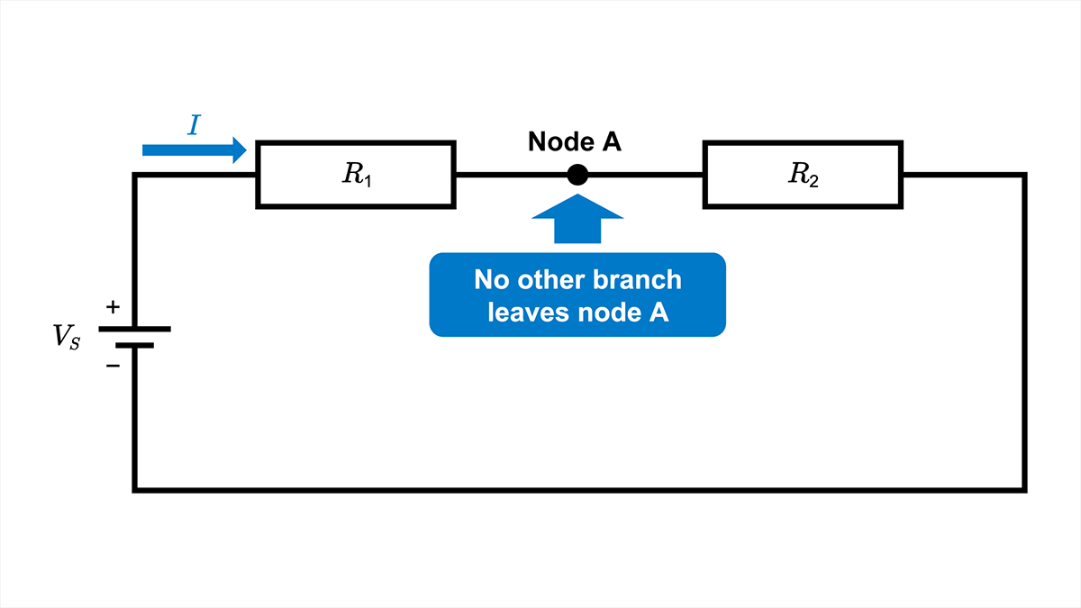 Figure 1. Two resistors connected in series with no branch at node A. Current I flows through R1 and R2 in sequence.
If a component or conductor in this path fails open, the only closed current path is interrupted. In the ideal circuit, the circuit current becomes 0 A.
A Branch Means the Components Are Not a Simple Series Pair
If another branch leaves the node shared by two components, the same current does not necessarily flow through both components. They therefore cannot be treated as a simple series pair. Figure 2 shows current division at node A after resistor R1. The current I through R1 equals the sum of branch currents I2 and IL.
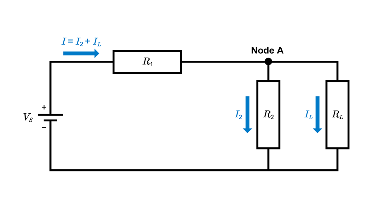 Figure 2. Current branches at node A, so R1 and R2 are not a simple series pair.
In this circuit, R2 and load resistance RL are connected between the same two nodes and are therefore in parallel. R1 is in series with the parallel equivalent of R2 and RL. The equivalent resistance must be calculated from the actual connection topology rather than by adding R1 and R2 alone.
Conversely, components can be connected in series even when they are drawn far apart. Series connection is determined by the node connections and current paths, not by the visual layout of the schematic.
Three Rules for a Series Circuit
A resistive series circuit follows three relationships: the same current flows through every resistor, the source voltage is divided among the resistors, and the resistor values add. These relationships follow from Ohm’s law and Kirchhoff’s laws applied to a current path with no branches.
The Same Current Flows Through Every Resistor
Every resistor in a series string carries the same current. For resistors R1 through Rn connected in series,
\(I=I_1=R_2=⋯=I_n\)
Because there is no branch between the resistors, current entering one resistor continues into the next. The resistor values determine the magnitude of the circuit current, but every resistor in the series string carries that same current. Different resistor values therefore produce different voltage drops.
Voltage Drops Add Up to the Source Voltage
When current I flows through resistor Ri, Ohm’s law gives the voltage drop Vi across that resistor:
\(V_i=IR_i\)
For a closed loop containing one source and several resistors, the sum of the resistor voltage drops equals the source voltage VS:
\(V_S=V_1+V_2+⋯+V_n\)
Because the same current flows through every resistor, the voltage drop is proportional to resistance. The voltage drop across Ri can also be written as
\(V_i=V_S\displaystyle \frac{R_i}{R_{total}}\)
This voltage-division relationship applies only when the same current flows through the resistor string. Connecting a load to an intermediate node creates a branch, so the loaded circuit must be recalculated.
Total Resistance Is the Sum of the Resistor Values
The total resistance, also called the equivalent resistance, is the resistance that can replace the entire series string. Because the current I is common to every resistor,
\(V_S=IR_1+IR_2+⋯+IR_n\)
Factoring out I
\(V_S=I(R_1+R_2+⋯+R_n)\)
Comparing this expression with Ohm’s law for the complete circuit, VS = IRtotal, gives
\(R_{total}=R_1+I_2+⋯+R_n\)
Adding another positive-valued resistor in series increases the total resistance. At a fixed source voltage, the circuit current therefore decreases. For the general relationship among voltage, current, resistance, and power, see Ohm’s Law: Voltage, Current, and Resistance.
How to Calculate a Series Circuit
First, identify the components that form one series-connected section. Calculate the total resistance of that section, then use it to find the circuit current. Use the common current to calculate each voltage drop and power dissipation, and verify the result with the voltage and power totals.
Calculate Total Resistance, Current, Voltage, and Power in This Order
The calculation is easier to follow in the following order:
- Add the resistor values to obtain total resistance Rtotal .
- Divide source voltage VS by total resistance to obtain circuit current I .
- Use the circuit current and each resistor value to obtain voltage drop Vi .
- Calculate power dissipation Pi for each resistor.
- Verify the calculation from the voltage and power totals.
Use the following equations:
\(R_{total}=R_1+R_2+⋯+R_n\)
\(I=\displaystyle \frac{V_S}{R_{total}}\)
\(V_i=IR_i\)
\(P_i=V_i I=I^2 R_i=\displaystyle \frac{V_i^2}{R_i}\)
Use consistent units for voltage, current, and resistance before substituting numerical values.
Worked Example: 12 V with 3.3 kΩ and 6.8 kΩ in Series
Entering this example in the Series Circuit Calculator should produce the same results shown below. A 12 V source is connected to R1 = 3.3 kΩ and R2 = 6.8 kΩ in series. The calculation finds total resistance, circuit current, each voltage drop, and each resistor’s power dissipation. Figure 3 shows the circuit. Wiring resistance and source internal resistance are ignored, and the resistor values are treated as nominal.
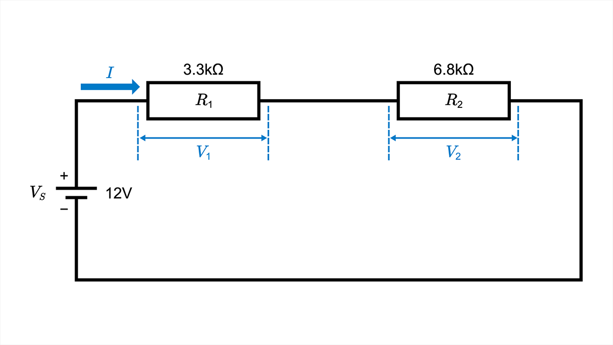 Figure 3. Series circuit used in the worked example: 12 V, 3.3 kΩ, and 6.8 kΩ.
Start with the general total-resistance equation, then substitute the resistor values.
\(R_{total}=R_1+R_2\)
\(R_{total}=3.3 kΩ+6.8 kΩ=10.1 kΩ\)
Next, apply Ohm’s law to the complete circuit.
\(I=\displaystyle \frac{V_S}{R_{total}}\)
\(I=\displaystyle \frac{12 V}{10.1 kΩ}≈1.188 mA \)
The following calculations retain 1.188 mA to limit rounding error. Calculate each voltage drop from Vi = IRi .
\(V_1=IR_1 \)
\(V_1=1.188 mA×3.3 kΩ≈3.92 V \)
\(V_2=IR_2 \)
\(V_2=1.188 mA×6.8 kΩ≈8.08 V \)
R2 has the larger resistance, so it also has the larger voltage drop.
Calculate each resistor’s power dissipation from Pi = I2Ri .
\(P_1=I^2 R_1 \)
\(P_1=(1.188 mA)^2×3.3 kΩ≈4.66 mW \)
\(P_2=I^2 R_2 \)
\(P_2=(1.188 mA)^2×6.8 kΩ≈9.60 mW \)
These values are calculated from nominal inputs. Actual current, voltage, and power vary with source-voltage accuracy, resistor tolerance, and other circuit conditions.
Verify the Voltage and Power Totals
First, verify that the sum of the resistor voltage drops equals the source voltage.
\(V_S=V_1+V_2 \)
\(V_S≈3.92 V+8.08 V=12.00 V \)
Next, calculate the total power dissipated by the resistors.
\(P_R=P_1+P_2 \)
\(P_R≈4.66 mW+9.60 mW=14.26 mW \)
The power supplied by the source is
\(P_S=V_S I \)
\(P_S=12 V×1.188 mA≈14.26 mW \)
Apart from rounding error, the total power dissipated by the resistors equals the power supplied by the source. If the checks do not agree, review the circuit topology, unit conversions, voltage signs, and rounding of intermediate values.
Series vs. Parallel Circuits
In a series circuit, the same current flows through every component. In a parallel circuit, every branch is connected across the same two nodes, so the same voltage appears across every branch. Figure 4 compares the two connection types.
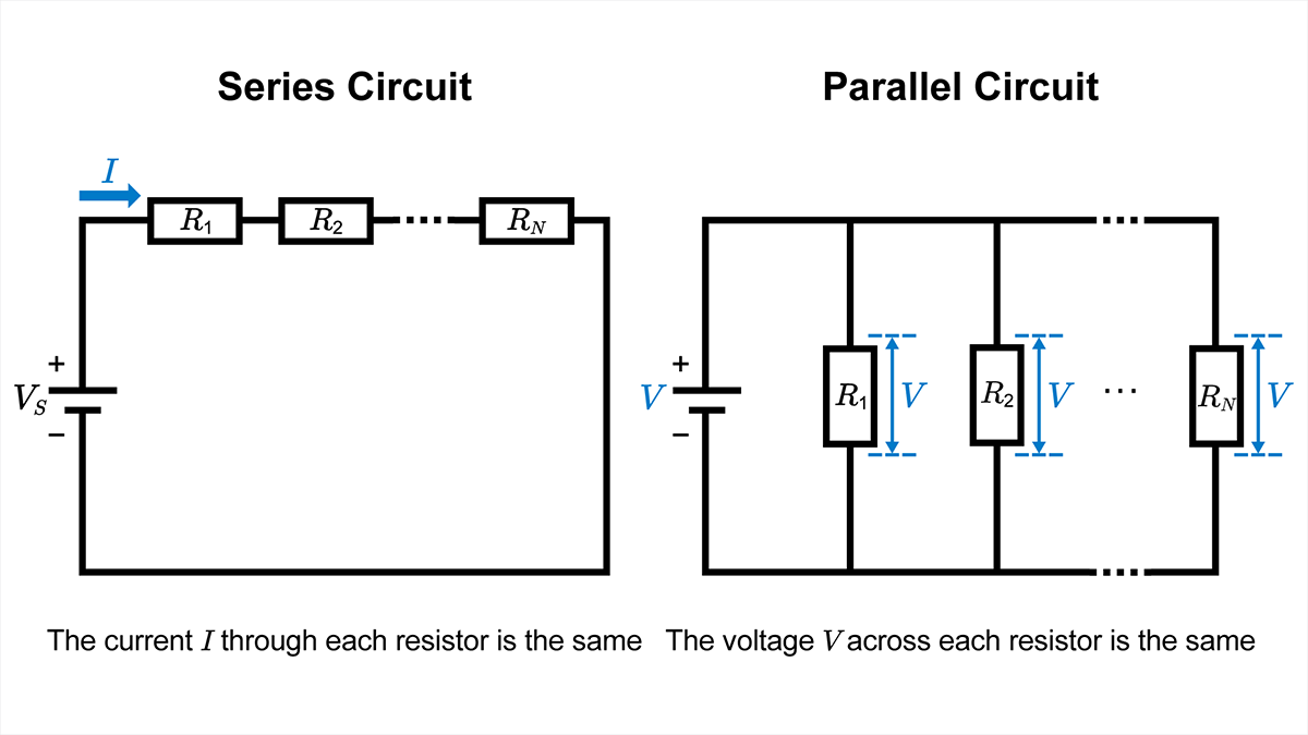 Figure 4. Connection, current, and voltage in series and parallel circuits.
| Comparison | Series circuit | Parallel circuit |
|---|---|---|
| Connection | Components are connected along one path, with no branch at the node between adjacent components. | Each branch is connected across the same two nodes. |
| Current | The same current flows through every component. | Total current divides among the branches. |
| Voltage | The voltage drops add up to the source voltage. | The same voltage is applied across every branch. |
| Equivalent resistance | Rtotal = R1 + R2 +⋯ | 1/Rtotal = 1/R1 + 1/R2 +⋯ |
| Open-circuit behavior | An open in the only current path stops current through the entire circuit. | One open branch does not necessarily stop current in the other branches. |
In a circuit that contains both series and parallel sections, identify components that carry the same current and branches connected across the same two nodes. Replace clearly reducible sections with their equivalent resistance one step at a time. Some networks, including bridge circuits, cannot be reduced by simple series and parallel combinations alone.
Related Applications of Series Connections
Series connections are used to divide voltage and to limit current. The detailed design depends on loading and on the electrical behavior of the connected components.
Voltage Divider Circuits
A voltage divider is one application of a series resistor network. When a load is connected to the output node, the lower resistor and the load form a parallel combination, so the circuit is no longer an unloaded two-resistor series string. Use the Voltage Divider Circuit guidance to include load resistance and select the resistor values.
LED Current-Limiting Resistors
A series resistor used with a low-power indicator LED can limit forward current from a voltage source. Because LED forward voltage varies with current, temperature, and device variation, do not treat the LED as a fixed resistor. Refer to LED Circuit Configuration when selecting the resistance and checking the operating range.
Practical Limits and Resistor Ratings
The worked example uses a fixed source voltage and nominal resistor values. For a real circuit, combine the minimum and maximum source voltage with resistor tolerance to determine the possible range of circuit current, voltage drop, and power dissipation. Include resistance temperature coefficient and wiring resistance when the required accuracy makes them significant.
Resistor power dissipation produces heat. Compare the worst-case Pi with the resistor’s rated power after applying the derating curve for the specified ambient or terminal temperature.
Also, verify that the voltage across each resistor is within the rated voltage and maximum element voltage limits stated in the datasheet. A resistor can meet its power limit while exceeding a voltage limit, particularly at high resistance values. For details on rated power and derating, see the Chip Resistor Specifications.
To calculate a series circuit, first identify the section in which the same current flows. Then calculate total resistance, circuit current, each voltage drop, and each power dissipation. Verify the result from the voltage and power totals. If a load or branch is added, recalculate the circuit from the updated node connections.
【Download Documents】 DC Circuit Fundamentals
This handbook summarizes the fundamental laws and circuit analysis methods of DC circuits covered in each article. It outlines derivations and circuit behavior, highlighting essential ideas for circuit design.
Electrical Circuit Design
Basic
- Seven Tools for Soldering
- Soldering Techniques and Solder Types
- Seven Techniques for Printed Circuit Board Reworking
-
AC Circuits Fundamentals: Article Guide
- AC Circuits: Alternating Current, Waveforms, and Formulas
- Complex Numbers in AC Circuit
- Fundamentals of Capacitive Circuits: Understanding Series and Parallel Capacitor Connections
- Electrical Reactance
- What is Impedance? AC Circuit Analysis and Design
- Impedance Measurement: How to Choose Methods and Improve Accuracy
- Impedance Matching: Why It Matters for Power Transfer and Signal Reflections
- Resonant Circuits: Resonant Frequency and Q Factor
- RLC Circuit: Series and Parallel, Applied circuits
- What is AC Power? Active Power, Reactive Power, Apparent Power
- Power Factor: Calculation and Efficiency Improvement
- What is PFC?
- Boundary Current Mode (BCM) PFC: Examples of Efficiency Improvement Using Diodes
- Continuous Current Mode (CCM) PFC: Examples of Efficiency Improvement Using Diode
- LED Illumination Circuits:Example of Efficiency Improvement and Noise Reduction Using MOSFETs
- PFC Circuits for Air Conditioners:Example of Efficiency Improvement Using MOSFETs and Diodes
-
DC Circuits Fundamentals: Article Guide
- Electric Current and Voltage in DC Circuits
- Ohm’s Law: Voltage, Current, and Resistance
- Series Circuit Calculator for Resistance, Current, Voltage Drop, and Power
- Kirchhoff’s Circuit Laws
- What Is Mesh Analysis (Mesh Current Method)?
- What Is Nodal Analysis (Nodal Voltage Analysis)?
- Thevenin’s Theorem: DC Circuit Analysis
- Norton’s Theorem: Equivalent Circuit Analysis
- What Is the Superposition Theorem?
- What Is the Δ–Y Transformation (Y–Δ Transformation)?
- Voltage Divider Circuit
- Current Divider and the Current Divider Rule