
Electrical Circuit Design|Basic
Parallel Resistor Calculator for Equivalent Resistance, Branch Current, and Power
2026.10.21
table of contents
- ・Parallel Resistor Calculator
- ・Parallel Resistance Formula
- ・Calculate Branch Current, Total Current, and Power from Source Voltage
- ・Worked Example: 3.3 kΩ and 6.8 kΩ in Parallel on a 12 V Source
- ・Identify a True Parallel Connection by Its Nodes
- ・Series vs. Parallel Circuits
- ・Why Connect Resistors in Parallel?
- ・Checks Before Applying the Results to a Real Circuit
- ・Summary
Use this parallel circuit calculator to find the equivalent resistance of two to ten resistors in parallel. Add a source voltage to calculate branch current, total current, and the power dissipated by each resistor.
This page covers resistor-only parallel circuits in steady-state DC. It derives the parallel-resistance formula, works through a numerical example, verifies voltage, current, and power balance, and identifies the ratings to check before applying the result to a real circuit.
Parallel Resistor Calculator
Enter two to ten resistor values. Source voltage is optional. With resistor values alone, the calculator returns equivalent resistance. When a source voltage is also entered, it adds current and power results.
Please check the following entries
Calculation results
Results will appear here
Enter R1 and R2, then select Calculate.
This calculator applies to purely parallel DC circuits in steady state, with ideal resistors greater than 0 Ω connected between the same two nodes. Series-parallel networks, bridge circuits, AC circuits, and circuits with LEDs or other non-resistive components are not covered.
This calculator applies to resistor-only circuits in which resistors greater than 0 Ω are connected across the same two nodes. It does not apply to series-parallel networks, bridge circuits, AC circuits, capacitors, inductors, or LEDs.
Enter the source voltage when branch current and power are required. Source voltage is not needed to calculate equivalent resistance alone.
Parallel Resistance Formula
In a resistor-only parallel circuit, the voltage across every branch equals the source voltage VS . From Ohm’s law, the branch current Ii through resistor Ri is:
\(I_i=\displaystyle \frac{V_S}{R_i}\)
By Kirchhoff’s current law (KCL), the total current Itotal supplied by the source equals the sum of the branch currents.
\(I_{total}=\displaystyle\sum_{i=1}^{n}I_i=\displaystyle\sum_{i=1}^{n}\frac{V_S}{R_i}=V_S\displaystyle\sum_{i=1}^{n}\frac{1}{R_i}\)
If the entire circuit is replaced by a single equivalent resistance Req , the same total current is:
\(I_{total}=\displaystyle \frac{V_S}{R_{eq}}\)
Because both equations describe the same total current, the equivalent resistance of a parallel circuit is given by:
\(\displaystyle \frac{1}{R_{eq}}=\displaystyle\sum_{i=1}^{n}\frac{1}{R_i}\)
\(R_{eq}=\displaystyle\frac{1}{\sum_{i=1}^{n}\displaystyle \frac{1}{R_i}}\)
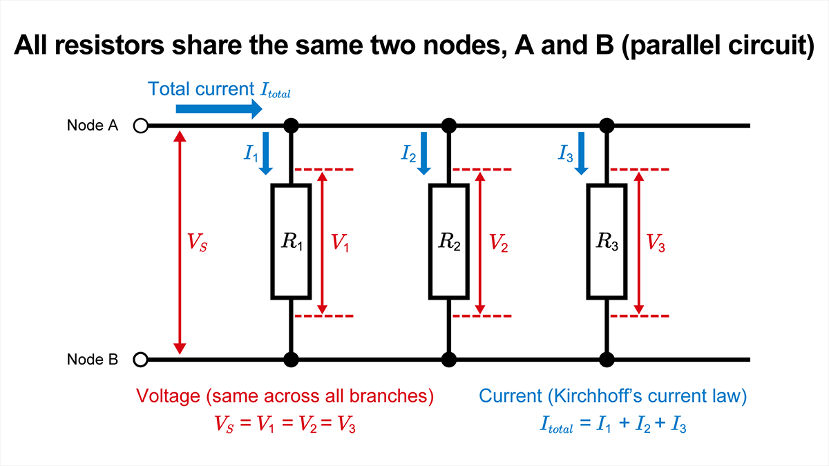 Figure 1. R1 , R2 , and R3 share the same two nodes, and total current divides among the branches.
In Figure 1, the total current Itotal divides into I1 , I2 , and I3 before recombining. Because R1 , R2 , and R3 are connected between the same nodes A and B, the voltage across each branch is the same.
Here, Ri is the resistance of branch i, and n is the number of parallel resistors. Convert all resistance values to a common unit before substitution. For example, when using 1 kΩ, 2.2 kΩ, and 470 Ω, convert them all to ohms or kilohms. The calculator converts each selected unit to ohms internally.
Two Resistors in Parallel
For two resistors, the general equation simplifies to:
\(R_{eq}=\displaystyle\frac{R_1 R_2}{R_1+R_2}\)
The numerator is the product of the two resistances, and the denominator is their sum. This product-over-sum form is convenient for hand calculations with two resistors, but it does not apply directly to three or more. Use the reciprocal-sum equation for three or more resistors.
Equal Resistors in Parallel
If n equal resistors, each with resistance R , are connected in parallel, the reciprocal sum is n/R . The equivalent resistance is therefore:
\(R_{eq}=\displaystyle\frac{R}{n}\)
For two identical resistors, this reduces to Req =R /2 . For example, four 1 kΩ resistors in parallel have an equivalent resistance of 250 Ω. With equal resistors in an ideal parallel circuit, branch current and power dissipation are also equal.
Check the Result Against the Smallest Resistor
For a resistor-only parallel circuit containing two or more positive resistances, the equivalent resistance is always less than the smallest branch resistance.
\(R_{eq}<\min(R_1,R_2,\ldots,R_n)\)
Each added parallel branch creates another current path and increases total conductance, so the equivalent resistance decreases. If a calculated result is greater than or equal to the smallest resistor value, check the unit conversion, equation, and input values.
Calculate Branch Current, Total Current, and Power from Source Voltage
When source voltage is entered, the calculator returns branch voltage and current, total current, power dissipated by each resistor, and the power supplied by the source in addition to equivalent resistance.
Branch Voltage and Branch Current
In a resistor-only parallel circuit, every branch is connected across the same two nodes. The voltage across each branch, Vi , therefore equals the source voltage, VS .
\(V_i=V_S\)
The same source voltage appears across every branch, but branch current depends on resistance.
\(I_i=\displaystyle\frac{V_S}{R_i}\)
At a fixed source voltage, a lower resistance draws a larger current. The branch resistance therefore determines how total current is distributed.
Total Current and Percentage of Total Current
The total current supplied by the source is the sum of all branch currents. It also equals the current calculated from equivalent resistance.
\(I_{total}=\displaystyle\sum_{i=1}^{n}I_i=\displaystyle\frac{V_S}{R_{eq}}\)
The percentage of total current in a branch is its branch current divided by total current. In general form, this is also the ratio of branch conductance to total conductance.
\(\displaystyle \frac{I_i}{I_{total}}=\frac{\displaystyle \frac{1}{R_i}}{\sum_{j=1}^{n}\displaystyle \frac{1}{R_j}}\)
For the current-divider formula for two resistors, , see Current Divider and the Current Divider Rule.
Power Dissipation and Balance Checks
The power dissipated by resistor i, Pi , is the product of branch voltage and branch current. For a resistive branch, the same value can be calculated from source voltage and resistance.
\(P_i=V_SI_i=\displaystyle \frac{V_S^2}{R_i}\)
The power supplied by the source Psource is the product of source voltage and total current. In an ideal circuit, it equals the sum of the power dissipated by all branches.
\(P_{source}=V_SI_{total}=\displaystyle \frac{V_S^2}{R_{eq}}=\displaystyle \sum_{i=1}^{n}P_i\)
The calculation can be checked against the following three relationships.
\(V_i=I_i R_i=V_S\)
\(\displaystyle\sum_{i=1}^{n}I_i=I_{total}=\frac{V_S}{R_{eq}}\)
\(\displaystyle \sum_{i=1}^{n}P_i=P_{source}=V_SI_{total}\)
The calculator uses unrounded values to verify that branch voltage, current balance, and power balance agree within a defined numerical tolerance. These checks confirm the internal consistency of the results calculated from the entered values. They do not predict measured values in a real circuit that includes resistor tolerance, wiring resistance, source resistance, or temperature effects.
Worked Example: 3.3 kΩ and 6.8 kΩ in Parallel on a 12 V Source
Consider a 3.3 kΩ resistor R1 and a 6.8 kΩ resistor R2 connected in parallel across a 12 V DC source.
| Input | Value |
|---|---|
| Source voltage VS | 12 V |
| Resistor R1 | 3.3 kΩ |
| Resistor R2 | 6.8 kΩ |
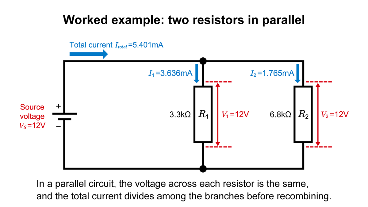 Figure 2. A 3.3 kΩ resistor and a 6.8 kΩ resistor connected in parallel across a 12 V source, showing branch current and total current.
Calculate Equivalent Resistance
For two resistors in parallel, use the product-over-sum form.
\(R_{eq}=\displaystyle \frac{R_1R_2}{R_1+R_2}\)
Substituting the values gives:
\(R_{eq}=\displaystyle \frac{3.3 kΩ×6.8 kΩ}{3.3 kΩ+6.8 kΩ}=2.2217 kΩ\)
The displayed value is:
\(R_{eq}≈2.222 kΩ\)
The equivalent resistance is less than both 3.3 kΩ and 6.8 kΩ, as required for a parallel combination.
Calculate Branch Current and Total Current
Divide the source voltage by each resistance to calculate branch current.
\(I_1=\displaystyle \frac{12 V}{3.3 kΩ}≈3.636 mA \)
\(I_2=\displaystyle \frac{12 V}{6.8 kΩ}≈1.765 mA \)
Total current is the sum of the branch currents.
\(I_{total}=I_1+I_2≈5.401 mA \)
Calculating total current from equivalent resistance gives the same value.
\(I_{total}=\displaystyle \frac{12 V}{2.222 kΩ}=5.401 mA \)
R1 carries 67.33% of the total current, and R2 carries 32.67%.
Calculate Power and Verify the Three Relationships
The power dissipated by each branch is the product of source voltage and branch current.
\(P_1=12 V×3.6364 mA≈43.64 mW \)
\(P_2=12 V×1.7647 mA≈21.18 mW \)
The power supplied by the source is:
\(P_{source}=12 V×5.4011 mA≈64.81 mW \)
The common branch voltage can be determined by multiplying branch current by resistance.
\(I_1R_1=12 V, I_2R_2=12 V \)
The sum of the branch currents is 5.401mA, and the sum of the branch powers is 64.81 mW. These values agree with the total current calculated from equivalent resistance and the power supplied by the source.
| Branch | Resistance | Branch voltage | Branch current | Percentage of total current | Power dissipation |
|---|---|---|---|---|---|
| R1 branch | 3.3 kΩ | 12 V | 3.636 mA | 67.33% | 43.64 mW |
| R2 branch | 6.8 kΩ | 12 V | 1.765 mA | 32.67% | 21.18 mW |
| Entire circuit | 2.222 kΩ (equivalent resistance) | 12 V | 5.401 mA | 100.0% | 64.81 mW |
The table shows rounded display values. The checks use unrounded values.
Identify a True Parallel Connection by Its Nodes
A parallel connection is determined by the nodes connected to the two ends of each resistor, not by how the schematic is drawn. Resistors can be far apart on the diagram and still be parallel if both ends connect to the same two nodes. Conversely, resistors that appear side by side are not in parallel if their end nodes differ.
In Figure 1, the top ends of R1 , R2 , R3 are connected to node A, and the bottom ends are connected to node B. Because this condition is met, all three resistance values can be entered directly into the general parallel-resistance equation.
Do Not Treat a Series-Parallel Network as a Simple Parallel Circuit
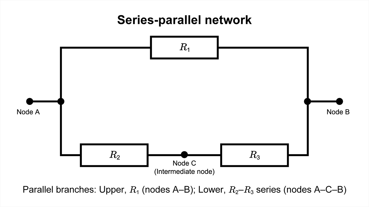 Figure 3. R1 is in parallel with the series branch formed by R2 and R3 .
In Figure 3, R1 is connected between nodes A and B. The lower branch contains R2 and R3 in series, and the right end of R2 connects to intermediate node C. Therefore, R1 and R2 are not connected across the same two nodes and cannot be entered as separate parallel resistors in the calculator.
First, combine R2 and R3 as a series resistance, then calculate the parallel combination of that result with R1 . Some circuits, including bridge networks, cannot be reduced using only simple series and parallel combinations. Check the two end nodes of each resistor before choosing the calculation method.
Series vs. Parallel Circuits
In a series circuit, the same current flows through every resistor. In a parallel circuit, the voltage across every resistor is the same. Identifying the connection and the common electrical quantity helps prevent using the wrong equation.
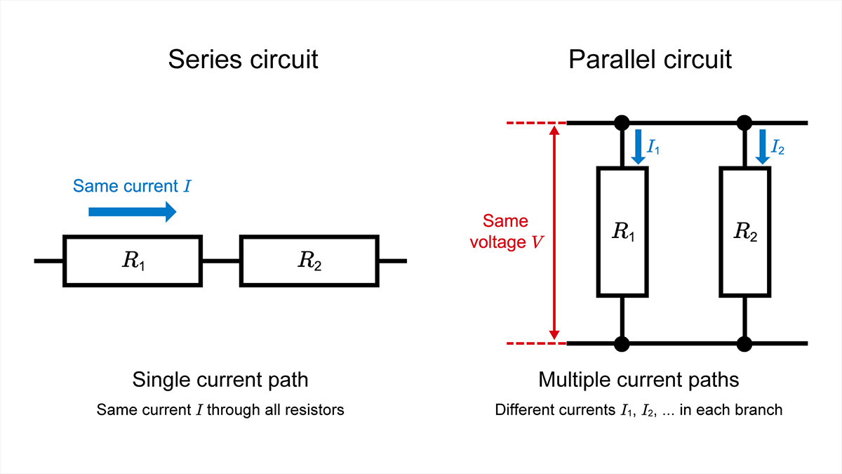 Figure 4. Connection topology and common electrical quantities in series and parallel circuits.
| Comparison | Series circuit | Parallel circuit |
|---|---|---|
| Connection | Resistors connected one after another in a single path | Each resistor connected across the same two nodes |
| Common electrical quantity | Current | Voltage |
| Equivalent resistance | Sum of all resistances | Reciprocal of the sum of reciprocals |
| After adding a resistor | Equivalent resistance increases | Equivalent resistance decreases |
| If one resistor opens | The current path is broken, so no current flows in the entire circuit | Other branches continue to conduct if the source and shared conductors remain intact |
The equations and worked examples for series circuits are covered in the Series Circuit article.
Why Connect Resistors in Parallel?
Resistors are connected in parallel mainly to obtain a resistance lower than any single resistor or to distribute power dissipation among multiple resistors. In either case, every resistor must be connected across the same two nodes and must individually remain within its ratings.
Obtain a lower equivalent resistance. The equivalent resistance of parallel-connected resistors is lower than the smallest branch resistance. Standard resistor values can be combined to approach a value that is not readily available as a single part. When accuracy matters, include resistor tolerance and temperature coefficient in the evaluation.
Distribute power dissipation among multiple resistors. Equal resistors connected under the same electrical conditions ideally carry equal current and dissipate equal power. In a real circuit, resistor tolerance, temperature differences, and PCB thermal conditions can make the distribution uneven. Do not rely only on the sum of the rated powers; verify the branch power and thermal conditions for each resistor.
In a parallel connection, the full source voltage appears across every resistor. Parallel connection therefore cannot be used to increase the allowable voltage of the resistor network. Each resistor must individually satisfy its applicable voltage rating.
Checks Before Applying the Results to a Real Circuit
The calculator assumes ideal resistors, an ideal voltage source, steady-state operation, and nominal resistance values. Before applying the results to a real circuit, review the current path from the source to each branch, the power, voltage, and temperature conditions of every resistor, resistance variation, and fault behavior.
Current Capacity of the Source and Shared Conductors
Adding a parallel branch reduces equivalent resistance and increases total current at the same source voltage. Check not only the source output-current capability, but also the ratings of shared conductors, connectors, switches, and protection devices that carry total current.
If wiring or contact resistance is not negligible, branch voltage can deviate from the ideal value. In high-current circuits, also evaluate conductor width and length, voltage drop at connections, and resulting heat.
Power, Voltage, and Temperature Limits for Each Resistor
Because the same voltage appears across every branch, the lower-resistance branch carries more current and dissipates more power. For each resistor, compare calculated branch power with rated power, applied voltage with the applicable voltage rating, and the operating temperature with the specified derating conditions.
Ratings and derating conditions vary by product. Confirm allowable values in the latest data sheet and official documentation for the selected resistor.
Tolerance, Temperature Effects, and Fault Conditions
Actual resistance varies from nominal value within the specified tolerance. Depending on the required accuracy, worst-case analysis or measurement may need to include temperature coefficient, self-heating, wiring resistance, and contact resistance.
If one branch opens, current in that branch becomes zero. Other branches continue to conduct as long as the source and shared conductors remain intact.
If a branch is shorted, an ideal voltage source would produce infinite current, so the calculator does not accept 0 Ω. In a real circuit, source and wiring resistance limit the current to a finite value, but not necessarily to a safe value. If protection does not operate, wiring and components can overheat or be damaged.
| Check | Value from calculator | Additional real-circuit check |
|---|---|---|
| Source and shared conductors | Total current Itotal | Source capacity, conductor width, connector, switch, and protection-device ratings |
| Each resistor | Branch current Ii , branch power Pi , and branch voltage Vi | Rated power, voltage rating, derating, and operating temperature |
| Calculation accuracy | Results based on nominal resistance values | Tolerance, temperature coefficient, self-heating, wiring resistance, and contact resistance |
| Fault conditions | Out of scope (normal operation only) | Open- and short-circuit current paths, protection behavior, and failure mode |
Summary
A parallel circuit connects multiple branches across the same two nodes. The voltage across every branch is the same, and total current equals the sum of the branch currents. For a resistor-only parallel circuit, equivalent resistance is calculated from the reciprocal sum of the branch resistances. The result is lower than the smallest resistance in the network.
When source voltage is known, Ohm’s law gives branch current, total current, and the power dissipated by each resistor. The result can be verified by checking that each branch voltage equals source voltage, the sum of branch currents equals total current, and the sum of branch powers equals the power supplied by the source.
Before applying the result to a real circuit, check the current capacity of the source and shared conductors, the power and voltage ratings and derating conditions of each resistor, resistance tolerance, and temperature conditions. Also confirm the nodes at both ends of each resistor so that a series-parallel or bridge network is not mistaken for a simple parallel circuit.
The calculator finds equivalent resistance for two to ten resistors. When source voltage is entered, it also calculates branch current, total current, power dissipation, and the associated balance checks.
【Download Documents】 DC Circuit Fundamentals
This handbook summarizes the fundamental laws and circuit analysis methods of DC circuits covered in each article. It outlines derivations and circuit behavior, highlighting essential ideas for circuit design.
Electrical Circuit Design
Basic
- Seven Tools for Soldering
- Soldering Techniques and Solder Types
- Seven Techniques for Printed Circuit Board Reworking
-
AC Circuits Fundamentals: Article Guide
- AC Circuits: Alternating Current, Waveforms, and Formulas
- Complex Numbers in AC Circuit
- Fundamentals of Capacitive Circuits: Understanding Series and Parallel Capacitor Connections
- Electrical Reactance
- What is Impedance? AC Circuit Analysis and Design
- Impedance Measurement: How to Choose Methods and Improve Accuracy
- Impedance Matching: Why It Matters for Power Transfer and Signal Reflections
- Resonant Circuits: Resonant Frequency and Q Factor
- RLC Circuit: Series and Parallel, Applied circuits
- What is AC Power? Active Power, Reactive Power, Apparent Power
- Power Factor: Calculation and Efficiency Improvement
- What is PFC?
- Boundary Current Mode (BCM) PFC: Examples of Efficiency Improvement Using Diodes
- Continuous Current Mode (CCM) PFC: Examples of Efficiency Improvement Using Diode
- LED Illumination Circuits:Example of Efficiency Improvement and Noise Reduction Using MOSFETs
- PFC Circuits for Air Conditioners:Example of Efficiency Improvement Using MOSFETs and Diodes
-
DC Circuits Fundamentals: Article Guide
- Electric Current and Voltage in DC Circuits
- Ohm’s Law: Voltage, Current, and Resistance
- Series Circuit Calculator for Resistance, Current, Voltage Drop, and Power
- Parallel Resistor Calculator for Equivalent Resistance, Branch Current, and Power
- Kirchhoff’s Circuit Laws
- What Is Mesh Analysis (Mesh Current Method)?
- What Is Nodal Analysis (Nodal Voltage Analysis)?
- Thevenin’s Theorem: DC Circuit Analysis
- Norton’s Theorem: Equivalent Circuit Analysis
- What Is the Superposition Theorem?
- What Is the Δ–Y Transformation (Y–Δ Transformation)?
- Voltage Divider Circuit
- Current Divider and the Current Divider Rule