Engineer Column
Harmonizing Circuit Design and EMC DesignPart 17 EMC Calculation Methods and EMC Simulations (2): Trial Calculation of Conducted Emissions (CE)
2023.01.25
Hello! I’m Inagaki, at ROHM.
In this 17th column, I would like to explain the most basic calculation method and simulation for electromagnetic compatibility (EMC), which is the trial calculation of conducted emission (CE). This is the “1 Ω/150 Ω method” in the IEC 61967-4 standard relating to electromagnetic compatibility (EMC) characteristics for a semiconductor integrated circuit (LSI).
The major international standards applicable to electromagnetic compatibility (EMC) are the IEC standards, the CISPR standards, and the ISO standards. IEC standards for the International Electrotechnical Commission, and the abovementioned 1 Ω/150 Ω method is also called the VDE method.
In this method, a spectrum is measured with the equivalent of 1 Ω connected to the ground pin of the semiconductor integrated circuit (LSI) and a network that is the equivalent of 150 Ω connected to the power supply pin, signal pins and the like. Note, however, that this method is not suitable for semiconductor integrated circuits (LSIs) with large power supply currents, where the voltages generated at both ends of 1Ω at the ground pin becomes so large that it interferes with basic operation. There are limiting values stipulated for electromagnetic interference (emissions), and if actual figures are not within these limits, a product cannot be said to conform to the relevant standard. Originally, IEC standards and other standards specify the measurement method, and the limit values are provided as reference examples. However, in general use, the limiting values are regarded as the standard values.
Well then, let’s move on to the EMC calculation method and EMC simulations. As explained previously, the IEC 61967-4 standard is a simple method to measure the supply current and signal currents of semiconductor integrated circuits (LSI) in terms of electromagnetic compatibility (EMC). The calculation procedure is as follows.
- ① Perform a transient analysis of the supply current and other currents of the semiconductor integrated circuit (LSI), and create a PWL (piecewise linear) waveform over one stable period. This serves as the IA model (internal activity model) or electromagnetic interference (EMI) model of the previous article (Part 16).
- ② Repetition of the PWL waveform for the current is set, a prescribed network (for the case of 150 Ω, 120 Ω + 6.8 nF + 51 Ω, or similar) is connected, and after performing the transient analysis, a fast Fourier transform (FFT) is performed.
- ③ After a unit conversion (dBμV), the results are graphed together with the limit values on the spec sheet, and standard conformance or nonconformance is judged.
I think that this much calculation could be automated by writing a script or macros that could be used within a circuit analysis tool. When performing measurements, a spectrum analyzer is connected, and so when calculations are to be performed, the input impedance of 50 Ω must be further connected (here mistakes are easily made, so be careful!).
Upon confirming that there is conformance to a standard, you may pat yourself on the back; but if conformance is not achieved, countermeasures must be taken. These may include improvements to ① above, that is, selecting the operation mode and redesigning the silicon chip, or, in ②, modifying the type and value of the product-dependent decoupling capacitor (CD), or the like.
The calculation method explained here can be tried using a circuit analysis tool, does not require measured values, can be automated using simple macros or scripts, conforms to the IEC 62433 standard, does not use data assimilation, and does not use noise elimination. Below are shown diagrams to serve as references for measurements and calculations.
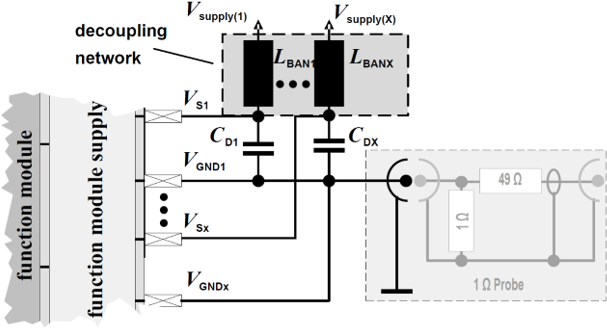
Example of an IEC 61967-4 standard 1 Ω method measurement circuit/calculation circuit
(LBAN1 =5 μH, CD1: product-dependent)
(Source: Generic_IC_EMC_Test_Specification_2.1_180713_ZVEI.pdf)
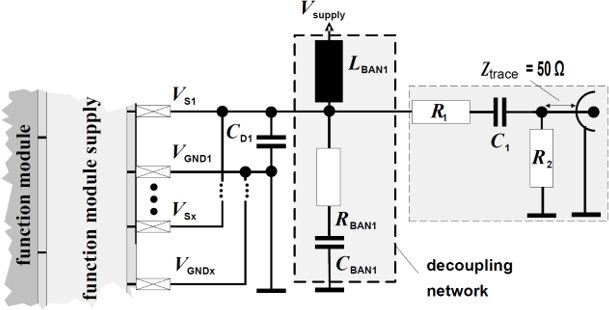
Example of an IEC 61967-4 standard 150 Ω method measurement circuit/calculation circuit
(R1=120 Ω, C1=6.8 nF, R2=51 Ω, LBAN1 =5 μH, CD1: product dependent, RBAN1: open, CBAN1: open)
(Source: Generic_IC_EMC_Test_Specification_2.1_180713_ZVEI.pdf)
Thank you for your kind attention.
【Download Documents】 Elementary EMC for Circuit Designers Working on EMC Issues
This handbook is designed to give designers who are going to work on EMC an idea of what EMC is. It promotes a sensible understanding of the relationship between EMC and the three perspectives of semiconductor devices, product specifications, and circuits and boards.

Engineer Column
-
Motor Current and Regeneration Current When Using a Single MOSFET in PWM Driving
-
Five Engineers Talk About New Medium-Power Device Products: Part 1 Development of Bipolar Transistors for Gate Driving in Inverter Circuits for xEVs
- Part 2 Fifth-Generation -40 V/-60 V P-channel Power MOSFETs with Greatly Reduced On-Resistance
- Part 3 Super junction MOSFETs Achieve Low On-Resistance, Fast Switching with High 650 V Voltage Rating
- Part 4 Power Diodes Achieve Improved Heat Dissipation Performance, Compactness through Adoption of PMDE Package
- Part 5 The DFN2020WF Package, Developed for External MOSFETs for Automotive Primary Power Supply ICs
-
Evolution and Kinds of Motors
- Features and Selective Use of Sensored and Sensorless Driving of Brushless Motors
- The Role of Brushless Motor Position Sensors and Notes on Their Placement
- Absolute Maximum Ratings of Motor Drivers
- Output Current of Motor Drivers in Actual Use
- Method of Calculating the Power Consumption of a Brushed Motor Driver: Part 1
- Method of Calculating the Power Consumption of a Brushed Motor Driver: Part 2
- Methods for Easily Driving Brushed DC Motors
- Motor Constant-Current Operation through PWM Driving
- Methods and Differences in Current Regeneration for PWM Driving of Brushed Motors
- Conditions for the Maximum Flow of Current in a Motor
- Power Consumption when Current is Regenerated in a Parasitic Diode of a Motor Driver Output Transistor
- Relations between Load Torque, Rotation Rate, and Motor Current of Brushed DC Motors
- PWM Driving of Motors: Relationship between PWM Period and Electrical Time Constant of the Motor
-
Highly Efficient Motor Driving is the Key to the EV Revolution
-
Harmonizing Circuit Design and EMC Design: Introduction
- Part 2 Summary of Semiconductors (2) Semiconductor Integrated Circuits (LSIs, ICs)
- Part 3 Summary of Semiconductors (3) Semiconductor Integrated Circuit (LSI, IC) Modules
- Part 4 Product Specifications (1) Product Specifications of Semiconductor Integrated Circuits
- Part 5 Product Specifications (2) ?How to Read Product Specifications
- Part 6 Product Specifications (3) Examples of General EMC Evaluation Indexes
- Part 7 Evaluation Circuits and Boards (1) Using Evaluation Boards
- Part 8 Evaluation Circuits and Boards (2) Handling of Ground Wires (GND)
- Part 9 Evaluation Circuits and Boards (3) Electromagnetic Interference (EMI) and Electromagnetic Susceptibility (EMS)
- Part 10 Websites (1) The Latest Information, Introduction of Major Products, Product Specs
- Part 11 Websites (2) Application Notes and Design Models
- Part 12 Websites (3) Design Support Tools
- Part 13 EMC Overview (1) What is Electromagnetic Compatibility?
- Part 14 EMC Overview (2) What is Electromagnetic Compatibility?
- Part 15 EMC Overview (3) What is Electromagnetic Compatibility?
- Part 16 EMC Calculation Methods and EMC Simulations (1): Overview of Calculation Methods
- Part 17 EMC Calculation Methods and EMC Simulations (2): Trial Calculation of Conducted Emissions (CE)
- Part 18 EMC Calculation Methods and EMC Simulations (3): Trial Calculation of Radiated Emissions (RE)
- Part 19 EMC Calculation Methods and EMC Simulations (4): Trial Calculation of Conducted Immunity (CI)
- Part 20 EMC Calculation Methods and EMC Simulations (5): Trial Calculation of Conducted Immunity (CI)
- Part 21 EMC Calculation Methods and EMC Simulations (6): Trial Calculation of Radiated Immunity (RI)
- Part 22 EMC Calculation Methods and EMC Simulations (7): Graphical User Interfaces (GUIs)
- Part 23 EMC Calculation Methods and EMC Simulations (8): Three-Dimensional (3D) Plots
- Part 24 EMC Calculation Methods and EMC Simulations (9): GNU Tools Used in Calculation Methods
- Part 1 Summary of Semiconductors (1) Transistors and Diodes