Engineer Column
Motor NotesMotor Constant-Current Operation through PWM Driving
2022.10.05
Representative motor driving methods include voltage driving, current driving, and PWM driving. In this article, PWM constant-current operation is discussed.
About PWM Constant-Current Operation
When a motor is driven by a constant current, what kind of operation results? In constant-current driving, the motor can be rotated at a constant torque. The motor torque is the product of the torque constant and the motor current. That is, the motor torque is proportional to the current, and so if the current is constant, the torque will likewise be constant.
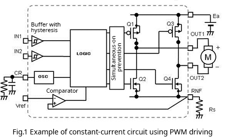
To begin with, Fig. 1 shows an example of a circuit for constant-current operation using PWM driving. This is a motor driver circuit that has an H bridge using four switches, for example MOSFETs, as the output stage. H bridges are explained in detail in the Basic Knowledge area of Tech Web, which can be accessed here.
Further, PWM driving is essentially a method for supplying the required power by turning pulses on and off. The height (voltage) of the pulses and their frequency are constant; the on-pulse width (time) is adjusted to control the power supplied. For details, please refer to this area of the Basic Knowledge area of Tech Web.
From this point, how the circuit presented above actually operates will be explained.
Fig. 1 assumes forward rotation. In this case, of the pair of MOSFETs Q1 and Q2, Q1 is turned on and Q2 is turned off, while OUT1 is connected to the power supply voltage Ea and current flows to the positive pole of the motor. At the same time, among the pair Q3 and Q4, Q3 is off and Q4 is on, and OUT2 is connected to GND via Rs at the driver RNF pin. This is the energizing state in which current flows from power supply to motor.
Here the objective is constant-current operation, and so the current must be controlled so as to be constant; this is accomplished by Rs and the comparator. Rs is a current detection resistor. The comparator compares the voltage equal to Rs multiplied by the motor current with the reference voltage applied to the reference voltage pin Vref. The reference voltage is set to Rs multiplied by the desired constant current value.
Energization causes the motor current to increase gradually, and when the Rs detection voltage exceeds Vref, the comparator turns Q1 off (the paired Q2 may remain off, or may be turned on), and energization of the motor is stopped.
When energization stops, the motor current initially continues to flow, but gradually decreases. After a certain time, when Q1 is again turned on and the motor is energized, the motor current again begins to increase, and when the Rs detection voltage exceeds Vref, Q1 is again turned off to stop energization, repeating the cycle. In the driver in Fig. 1 counts the frequency of the oscillator (OSC), and an arbitrary off time (toff) is set. The operation waveforms are shown in Fig. 2.
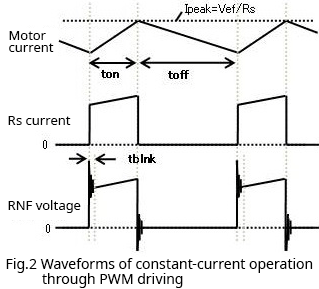
Through this repeated operation, a triangular wave current flows, the vertex of which is the current value obtained by dividing Vref by Rs. If the off time (toff) of Q1 is set to be sufficiently short, it is possible to pass what is substantially a constant current, that is, constant-current operation is possible.
The above has been an explanation of PWM constant-current operation of a motor. In actual driving, somewhat finer control is needed. For example, while energization is stopped and the regeneration current is flowing, a current does not flow in Rs, and so when energization is resumed, there is a large change in the current flowing in Rs. Because a parasitic inductance is always present, when this current is turned on or off, substantial voltage noise, like that in the waveform shown (see Fig. 2), occurs at the RNF pin, and a current that charges the parasitic capacitance of the MOSFET flows, possibly causing Vref to be exceeded. In order to prevent erroneous turn-off operation caused by such voltage noise, it is necessary to provide a short time period (tblnk) during which the peak current is ignored and there is no response, or a filter must be provided to eliminate noise, or some other measure must be used.
【Download Documents】 Basics of Brushed DC Motors and Drive Methods
Brushed DC motors are the most versatile motors and are used in a great many applications. This handbook provides the basics of brushed DC motors, explaining their construction, principle of operation, characteristics, and driving methods.

Engineer Column
-
Motor Current and Regeneration Current When Using a Single MOSFET in PWM Driving
-
Five Engineers Talk About New Medium-Power Device Products: Part 1 Development of Bipolar Transistors for Gate Driving in Inverter Circuits for xEVs
- Part 2 Fifth-Generation -40 V/-60 V P-channel Power MOSFETs with Greatly Reduced On-Resistance
- Part 3 Super junction MOSFETs Achieve Low On-Resistance, Fast Switching with High 650 V Voltage Rating
- Part 4 Power Diodes Achieve Improved Heat Dissipation Performance, Compactness through Adoption of PMDE Package
- Part 5 The DFN2020WF Package, Developed for External MOSFETs for Automotive Primary Power Supply ICs
-
Evolution and Kinds of Motors
- Features and Selective Use of Sensored and Sensorless Driving of Brushless Motors
- The Role of Brushless Motor Position Sensors and Notes on Their Placement
- Absolute Maximum Ratings of Motor Drivers
- Output Current of Motor Drivers in Actual Use
- Method of Calculating the Power Consumption of a Brushed Motor Driver: Part 1
- Method of Calculating the Power Consumption of a Brushed Motor Driver: Part 2
- Methods for Easily Driving Brushed DC Motors
- Motor Constant-Current Operation through PWM Driving
- Methods and Differences in Current Regeneration for PWM Driving of Brushed Motors
- Conditions for the Maximum Flow of Current in a Motor
- Power Consumption when Current is Regenerated in a Parasitic Diode of a Motor Driver Output Transistor
- Relations between Load Torque, Rotation Rate, and Motor Current of Brushed DC Motors
- PWM Driving of Motors: Relationship between PWM Period and Electrical Time Constant of the Motor
-
Highly Efficient Motor Driving is the Key to the EV Revolution
-
Harmonizing Circuit Design and EMC Design: Introduction
- Part 2 Summary of Semiconductors (2) Semiconductor Integrated Circuits (LSIs, ICs)
- Part 3 Summary of Semiconductors (3) Semiconductor Integrated Circuit (LSI, IC) Modules
- Part 4 Product Specifications (1) Product Specifications of Semiconductor Integrated Circuits
- Part 5 Product Specifications (2) ?How to Read Product Specifications
- Part 6 Product Specifications (3) Examples of General EMC Evaluation Indexes
- Part 7 Evaluation Circuits and Boards (1) Using Evaluation Boards
- Part 8 Evaluation Circuits and Boards (2) Handling of Ground Wires (GND)
- Part 9 Evaluation Circuits and Boards (3) Electromagnetic Interference (EMI) and Electromagnetic Susceptibility (EMS)
- Part 10 Websites (1) The Latest Information, Introduction of Major Products, Product Specs
- Part 11 Websites (2) Application Notes and Design Models
- Part 12 Websites (3) Design Support Tools
- Part 13 EMC Overview (1) What is Electromagnetic Compatibility?
- Part 14 EMC Overview (2) What is Electromagnetic Compatibility?
- Part 15 EMC Overview (3) What is Electromagnetic Compatibility?
- Part 16 EMC Calculation Methods and EMC Simulations (1): Overview of Calculation Methods
- Part 17 EMC Calculation Methods and EMC Simulations (2): Trial Calculation of Conducted Emissions (CE)
- Part 18 EMC Calculation Methods and EMC Simulations (3): Trial Calculation of Radiated Emissions (RE)
- Part 19 EMC Calculation Methods and EMC Simulations (4): Trial Calculation of Conducted Immunity (CI)
- Part 20 EMC Calculation Methods and EMC Simulations (5): Trial Calculation of Conducted Immunity (CI)
- Part 21 EMC Calculation Methods and EMC Simulations (6): Trial Calculation of Radiated Immunity (RI)
- Part 22 EMC Calculation Methods and EMC Simulations (7): Graphical User Interfaces (GUIs)
- Part 23 EMC Calculation Methods and EMC Simulations (8): Three-Dimensional (3D) Plots
- Part 24 EMC Calculation Methods and EMC Simulations (9): GNU Tools Used in Calculation Methods
- Part 1 Summary of Semiconductors (1) Transistors and Diodes