Learn Know-how
Effective Use of Decoupling Capacitors Point 2
2018.12.06
Points of this article
・There are two main points to consider for the effective use of decoupling capacitors: (1) Use of multiple capacitors, and (2) lowering capacitor ESL values.
・By lowering the capacitor ESL, high-frequency characteristics are improved, and high-frequency noise can be more effectively attenuated.
・There are capacitors which, even for the same capacitance, have ESL values that are lowered through innovations in the size and structure.
In the previous article, as Point 1 in “Effective Use of Decoupling Capacitors”, we explained “Use of multiple decoupling capacitors”. In this article, we move on to Point 2.
- Effective Use of Decoupling (Bypass) Capacitors Point 1
- Point 2: Reducing the capacitor ESL (equivalent series inductance)
- Other matters to be noted
Point 2: Reducing the capacitor ESL
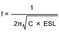
The second point in the effective use of decoupling capacitors is the approach of lowering the capacitor ESL, or equivalent series inductance. However, the ESL of a capacitor cannot itself be changed, and so lowering the ESL in effect means using a capacitor with the same electrostatic capacitance, but with a lower ESL. By lowering the ESL, the high-frequency characteristics are improved, and high-frequency noise can be more effectively decreased.
・Using a capacitor that has the same value but is smaller in size
Some multilayer ceramic capacitors (MLCCs) are made available as products having the same capacitance value, but in different-size packages. The ESL depends on the structure of the terminal portions. Smaller-size capacitors necessarily have smaller terminals, and so normally the ESL is smaller.
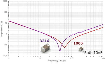
In noise countermeasures, when it is necessary to attenuate the noise at higher frequencies, one method is to select capacitors of smaller sizes.
・Using a capacitor with a lowered ESL
Among multilayer ceramic capacitors, there are types the ESL of which is lowered through innovations in the shape and structure.
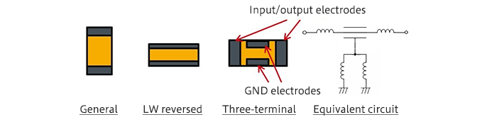
As shown in the graphic image, capacitors generally have electrodes on the short-edge sides; in contrast, LW reversed type capacitors have the electrodes on the long-edge sides. The name derives from the fact that the length (L) and the width (W) edges are reversed. By increasing the electrode width, the ESL is lowered.
A three-terminal capacitor is a capacitor obtained by modifying structure of a general (two-terminal) capacitor to improve the frequency characteristic. In a three-terminal capacitor, the other end of one of the terminals (electrodes) of a two-terminal capacitor is passed to the outside as a feed-through terminal, and the other terminal is used as a GND terminal. In the diagram above, the input/output electrodes correspond to a penetrating terminal both ends of which are drawn out, and the left and right electrodes are of course conducting. A dielectric is present between the input/output electrodes (feed-through terminals) and the GND electrode, so that the device functions as a capacitor.
The input/output terminals are connected in series with a power supply and a signal line (one of the input/output terminals is connected to the input side, and the other is connected to the output side), and the GND electrode is connected to ground. As a result, the ESL of the input/output terminals is not included on the ground side, and so the ground impedance is extremely low. Moreover, series insertion into the noise path means that the ESL of the input/output terminals contributes to reduce noise (increase the insertion loss).
By arranging a pair of GND electrodes on the long-edge sides, the ESL is kept small, and by using a parallel connection, the ESL is halved.
Using such a structure, a three-terminal capacitor can be designed with the ESR held low in addition to the extremely small ESL, the frequency characteristic can be improved dramatically compared with a two-terminal capacitor having the same capacitance value.
In the next article, we will explain a number of related points that should be noted.
【Download Documents】 Switching Power Supply Basic of EMC and Noise Countermeasures
This is a handbook on the basics of EMC (electromagnetic compatibility) and noise countermeasures for switching power supplies. Based on the understanding of the basics of noise, it explains the noise countermeasures using capacitors and inductors in switching power supplies.

Learn Know-how
Electrical Circuit Design
- Soldering Techniques and Solder Types
- Seven Tools for Soldering
- Seven Techniques for Printed Circuit Board Reworking
-
AC Circuits Fundamentals: Article Guide
- AC Circuits: Alternating Current, Waveforms, and Formulas
- Complex Numbers in AC Circuit
- Fundamentals of Capacitive Circuits: Understanding Series and Parallel Capacitor Connections
- Electrical Reactance
- What is Impedance? AC Circuit Analysis and Design
- Impedance Measurement: How to Choose Methods and Improve Accuracy
- Impedance Matching: Why It Matters for Power Transfer and Signal Reflections
- Resonant Circuits: Resonant Frequency and Q Factor
- RLC Circuit: Series and Parallel, Applied circuits
- What is AC Power? Active Power, Reactive Power, Apparent Power
- Power Factor: Calculation and Efficiency Improvement
- What is PFC?
- Boundary Current Mode (BCM) PFC: Examples of Efficiency Improvement Using Diodes
- Continuous Current Mode (CCM) PFC: Examples of Efficiency Improvement Using Diode
- LED Illumination Circuits:Example of Efficiency Improvement and Noise Reduction Using MOSFETs
- PFC Circuits for Air Conditioners:Example of Efficiency Improvement Using MOSFETs and Diodes
-
DC Circuits Fundamentals: Article Guide
- Ohm’s Law: Voltage, Current, and Resistance
- Electric Current and Voltage in DC Circuits
- Kirchhoff’s Circuit Laws
- What Is Mesh Analysis (Mesh Current Method)?
- What Is Nodal Analysis (Nodal Voltage Analysis)?
- Thevenin’s Theorem: DC Circuit Analysis
- Norton’s Theorem: Equivalent Circuit Analysis
- What Is the Superposition Theorem?
- What Is the Δ–Y Transformation (Y–Δ Transformation)?
- Voltage Divider Circuit
- Current Divider and the Current Divider Rule
Thermal design
-
About Thermal Design
- Changes in Engineering Trends and Thermal Design
- A Mutual Understanding of Thermal Design
- Fundamentals of Thermal Resistance and Heat Dissipation: About Thermal Resistance
- Fundamentals of Thermal Resistance and Heat Dissipation: Heat Transmission and Heat Dissipation Paths
- Fundamentals of Thermal Resistance and Heat Dissipation : Thermal Resistance in Conduction
- Fundamentals of Thermal Resistance and Heat Dissipation : Thermal Resistance in Convection
- Fundamentals of Thermal Resistance and Heat Dissipation : Thermal Resistance in Emission
- Thermal Resistance Data: JEDEC Standards, Thermal Resistance Measurement Environments, and Circuit Boards
- Thermal Resistance Data: Actual Data Example
- Thermal Resistance Data: Definitions of Thermal Resistance, Thermal Characterization Parameters
- Thermal Resistance Data: θJA and ΨJT in Estimation of TJ: Part 1
- Thermal Resistance Data: θJA and ΨJT in Estimation of TJ: Part 2
- Surface Temperature Measurements: Methods for Fastening Thermocouples
- Surface Temperature Measurements: Thermocouple Mounting Position
- Surface Temperature Measurements: Treatment of Thermocouple Tips
- Surface Temperature Measurements: Influence of the Thermocouple
- Estimating TJ: Basic Calculation Equations
- Estimating TJ: Calculation Example Using θJA
- Estimating TJ: Calculation Example Using ΨJT
- Estimating TJ: Calculation Example Using Transient Thermal Resistance
- Estimation of Heat Dissipation Area in Surface Mounting and Points to be Noted
- Surface Temperature Measurements: Thermocouple Types
- Summary
- Collection of Important Points Relating to Thermal Design
Switching Noise
- Procedures in Noise Countermeasures
- What is EMC?
-
Dealing with Noise Using Capacitors
- Understanding the Frequency Characteristics of Capacitors, Relative to ESR and ESL
- Measures to Address Noise Using Capacitors
- Effective Use of Decoupling (Bypass) Capacitors Point 1
- Effective Use of Decoupling Capacitors Point 2
- Effective Use of Decoupling Capacitors, Other Matters to be Noted
- Effective Use of Decoupling Capacitors, Summary
-
Dealing with Noise Using Inductors
- Frequency-Impedance Characteristics of Inductors and Determination of Inductor’s Resonance Frequency
- Basic Characteristics of Ferrite Beads and Inductors and Noise Countermeasures Using Them
- Dealing with Noise Using Common Mode Filters
- Points to be Noted: Crosstalk and Noise from GND Lines
- Summary of Dealing with Noise Using Inductors
- Other Noise Countermeasures
- Basics of EMC – Summary
Simulation
- Thermal Simulation of PTC Heaters
- Thermal Simulation of Linear Regulators
-
Foundations of Electronic Circuit Simulation Introduction
- About SPICE
- SPICE Simulators and SPICE Models
- Types of SPICE simulation: DC Analysis, AC Analysis, Transient Analysis
- Types of SPICE simulation: Monte Carlo
- Convergence Properties and Stability of SPICE Simulations
- Types of SPICE Model
- SPICE Device Models: Diode Example–Part 1
- SPICE Device Models: Diode Example–Part 2
- SPICE Subcircuit Models: MOSFET Example―Part 1
- SPICE Subcircuit Models: MOSFET Example―Part 2
- SPICE Subcircuit Models: Models Using Mathematical Expressions
- About Thermal Models
- About Thermal Dynamic Model
- Summary
-
About the ROHM Solution Simulator
- How to Access the ROHM Solution Simulator
- Trying Out the ROHM Solution Simulator (1)
- Trying Out the ROHM Solution Simulator (2)
- Starting a Simulation Circuit in the ROHM Solution Simulator
- ROHM Solution Simulator Toolbar Functions and Basic Operations
- ROHM Solution Simulator: User Interface
- Execution of Simulations
- Method for Displaying Simulation Results
- Simulation Result Display Tool: Wavebox
- Simulation Results Display Tool: Waveform Viewer
- Customization of Simulations
- Exporting Circuit Data to PartQuest™ Explorer
- Purchasing Samples for Evaluation
- Optimization of PFC Circuits
- Optimization of Inverter Circuits
- About Thermal Simulations of DC-DC Converters
- Circuit-Theory-Based Design Simulation