Learn Know-how
PFC Circuits: Examination of Appropriate Gate Driving Voltages
2021.08.18
Points of this article
・When a SiC MOSFET is used as a switching element, because the change in Ron with changes in the gate driving voltage VGS is considerable, the VGS setting is important.
・When studying the gate driving voltage VGS of a SiC MOSFET, a balance between efficiency and safety should be considered.
PFC Circuits: Examination of Appropriate Gate Driving Voltages
Here, appropriate values for the gate driving voltage VGS of a SiC MOSFET that is to be used as a switching element in a PFC circuit are examined.
Example Circuit
As an example circuit, the simulation circuit “A-2. PFC BCM Diode-Bridge-Less Vin=200V Iin=2.5A” in the Power Device Solution Circuit/AC-DC PFC list is used (see Fig. 9). Details of the circuit diagram can also be seen here.
In this example, simulations are used to examine an appropriate VGS value to drive the SCT2450KE SiC MOSFET shown in Fig. 9, which is the low-side switching element.
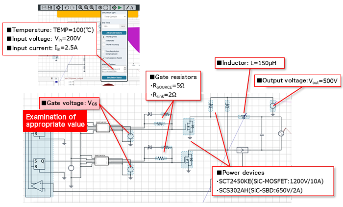
Fig.9 : “A-2. PFC BCM Diode-Bridge-Less Vin=200V Iin=2.5A” PFC simulation circuit
Relation between On Resistance and Gate Driving Voltage
As shown in Fig. 10, the on-resistance Ron of a conventional Si (silicon) MOSFET is essentially constant with respect to VGS while in the on state. In contrast, in the case of a SiC MOSFET Ron changes considerably depending on VGS, as shown in Fig. 11, and so the VGS setting is even more important than for a Si MOSFET. In other words, if the VGS value of a SiC MOSFET is too low, conduction losses increase and efficiency is worsened. Conversely, if VGS is set too high with the intention of improving efficiency, there is the concern that ratings may be exceeded. Hence it is extremely important that VGS be set appropriately.
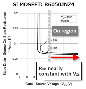
Fig. 10: Relation between Ron and VGS for a Si MOSFET
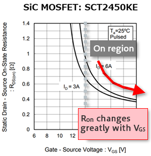
Fig. 11: Relation between Ron and VGS for a SiC MOSFET
Examination of Appropriate Gate Driving Voltages
Fig. 12 shows the results of simulation of the efficiency when the value of VGS for the SiC MOSFET in the PFC circuit of Fig. 9 is changed.
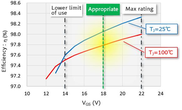
Fig. 12: Efficiency simulation results when the VGS of a SiC MOSFET is changed
When VGS is 14 V or lower, an increase in Ron causes the efficiency to drop sharply. This phenomenon is more prominent at lower temperatures; in this region there is a strong possibility of device failure, making use impossible. On the other hand, the higher the value of VGS, the better is the efficiency, but if the rated value (VGS = 22 V) is exceeded, use is not possible. Hence when considering a balance between efficiency and safety given these simulation results, we can say that a VGS of around 18 V is appropriate. And in actuality, it is recommended that ROHM SiC MOSFETs normally be used at a VGS of around 18 V.
Learn Know-how
Electrical Circuit Design
- Soldering Techniques and Solder Types
- Seven Tools for Soldering
- Seven Techniques for Printed Circuit Board Reworking
-
AC Circuits Fundamentals: Article Guide
- AC Circuits: Alternating Current, Waveforms, and Formulas
- Complex Numbers in AC Circuit
- Fundamentals of Capacitive Circuits: Understanding Series and Parallel Capacitor Connections
- Electrical Reactance
- What is Impedance? AC Circuit Analysis and Design
- Impedance Measurement: How to Choose Methods and Improve Accuracy
- Impedance Matching: Why It Matters for Power Transfer and Signal Reflections
- Resonant Circuits: Resonant Frequency and Q Factor
- RLC Circuit: Series and Parallel, Applied circuits
- What is AC Power? Active Power, Reactive Power, Apparent Power
- Power Factor: Calculation and Efficiency Improvement
- What is PFC?
- Boundary Current Mode (BCM) PFC: Examples of Efficiency Improvement Using Diodes
- Continuous Current Mode (CCM) PFC: Examples of Efficiency Improvement Using Diode
- LED Illumination Circuits:Example of Efficiency Improvement and Noise Reduction Using MOSFETs
- PFC Circuits for Air Conditioners:Example of Efficiency Improvement Using MOSFETs and Diodes
-
DC Circuits Fundamentals: Article Guide
- Ohm’s Law: Voltage, Current, and Resistance
- Electric Current and Voltage in DC Circuits
- Kirchhoff’s Circuit Laws
- What Is Mesh Analysis (Mesh Current Method)?
- What Is Nodal Analysis (Nodal Voltage Analysis)?
- Thevenin’s Theorem: DC Circuit Analysis
- Norton’s Theorem: Equivalent Circuit Analysis
- What Is the Superposition Theorem?
- What Is the Δ–Y Transformation (Y–Δ Transformation)?
- Voltage Divider Circuit
- Current Divider and the Current Divider Rule
Thermal design
-
About Thermal Design
- Changes in Engineering Trends and Thermal Design
- A Mutual Understanding of Thermal Design
- Fundamentals of Thermal Resistance and Heat Dissipation: About Thermal Resistance
- Fundamentals of Thermal Resistance and Heat Dissipation: Heat Transmission and Heat Dissipation Paths
- Fundamentals of Thermal Resistance and Heat Dissipation : Thermal Resistance in Conduction
- Fundamentals of Thermal Resistance and Heat Dissipation : Thermal Resistance in Convection
- Fundamentals of Thermal Resistance and Heat Dissipation : Thermal Resistance in Emission
- Thermal Resistance Data: JEDEC Standards, Thermal Resistance Measurement Environments, and Circuit Boards
- Thermal Resistance Data: Actual Data Example
- Thermal Resistance Data: Definitions of Thermal Resistance, Thermal Characterization Parameters
- Thermal Resistance Data: θJA and ΨJT in Estimation of TJ: Part 1
- Thermal Resistance Data: θJA and ΨJT in Estimation of TJ: Part 2
- Surface Temperature Measurements: Methods for Fastening Thermocouples
- Surface Temperature Measurements: Thermocouple Mounting Position
- Surface Temperature Measurements: Treatment of Thermocouple Tips
- Surface Temperature Measurements: Influence of the Thermocouple
- Estimating TJ: Basic Calculation Equations
- Estimating TJ: Calculation Example Using θJA
- Estimating TJ: Calculation Example Using ΨJT
- Estimating TJ: Calculation Example Using Transient Thermal Resistance
- Estimation of Heat Dissipation Area in Surface Mounting and Points to be Noted
- Surface Temperature Measurements: Thermocouple Types
- Summary
- Collection of Important Points Relating to Thermal Design
Switching Noise
- Procedures in Noise Countermeasures
- What is EMC?
-
Dealing with Noise Using Capacitors
- Understanding the Frequency Characteristics of Capacitors, Relative to ESR and ESL
- Measures to Address Noise Using Capacitors
- Effective Use of Decoupling (Bypass) Capacitors Point 1
- Effective Use of Decoupling Capacitors Point 2
- Effective Use of Decoupling Capacitors, Other Matters to be Noted
- Effective Use of Decoupling Capacitors, Summary
-
Dealing with Noise Using Inductors
- Frequency-Impedance Characteristics of Inductors and Determination of Inductor’s Resonance Frequency
- Basic Characteristics of Ferrite Beads and Inductors and Noise Countermeasures Using Them
- Dealing with Noise Using Common Mode Filters
- Points to be Noted: Crosstalk and Noise from GND Lines
- Summary of Dealing with Noise Using Inductors
- Other Noise Countermeasures
- Basics of EMC – Summary
Simulation
- Thermal Simulation of PTC Heaters
- Thermal Simulation of Linear Regulators
-
Foundations of Electronic Circuit Simulation Introduction
- About SPICE
- SPICE Simulators and SPICE Models
- Types of SPICE simulation: DC Analysis, AC Analysis, Transient Analysis
- Types of SPICE simulation: Monte Carlo
- Convergence Properties and Stability of SPICE Simulations
- Types of SPICE Model
- SPICE Device Models: Diode Example–Part 1
- SPICE Device Models: Diode Example–Part 2
- SPICE Subcircuit Models: MOSFET Example―Part 1
- SPICE Subcircuit Models: MOSFET Example―Part 2
- SPICE Subcircuit Models: Models Using Mathematical Expressions
- About Thermal Models
- About Thermal Dynamic Model
- Summary
-
About the ROHM Solution Simulator
- How to Access the ROHM Solution Simulator
- Trying Out the ROHM Solution Simulator (1)
- Trying Out the ROHM Solution Simulator (2)
- Starting a Simulation Circuit in the ROHM Solution Simulator
- ROHM Solution Simulator Toolbar Functions and Basic Operations
- ROHM Solution Simulator: User Interface
- Execution of Simulations
- Method for Displaying Simulation Results
- Simulation Result Display Tool: Wavebox
- Simulation Results Display Tool: Waveform Viewer
- Customization of Simulations
- Exporting Circuit Data to PartQuest™ Explorer
- Purchasing Samples for Evaluation
- Optimization of PFC Circuits
- Optimization of Inverter Circuits
- About Thermal Simulations of DC-DC Converters
- Circuit-Theory-Based Design Simulation