Learn Know-how
Types of SPICE simulation: Monte Carlo
2018.12.20
Points of this article
・SPICE-based simulators are provided with functions for DC analysis, AC analysis, transient analysis, Monte Carlo analysis, S parameters, Fourier analysis, noise analysis, and the like.
・Monte Carlo is a general term used for methods in which random numbers are employed in simulations and numerical calculations, and is used to take component variation into consideration.
・Monte Carlo settings are different depending on the simulator.
In the previous article we described SPICE simulation types and explained DC analysis, AC analysis, and transient analysis among the four types of analysis functions provided as standard. In this article, we explain the remaining function, Monte Carlo simulations.
SPICE simulation: Monte Carlo
Monte Carlo is a general term for methods using random numbers in simulations and numerical calculations. Nearly all the components used to create actual circuits–resistors, capacitors, inductors, diodes, transistors, ICs, and so on–have characteristics with variations. For example, a resistor has a tolerance: the resistance value of a resistor that is nominally 100 Ω with a precision of ±5% is between 95 Ω and 105 Ω. There is variation in each individual component, and the sum of the variations of the components results in variation in the characteristics of the circuit.
In a Monte Carlo simulation, simulations that reflect the variation in the different circuit elements are executed a number of times, and variation in the overall characteristics can be evaluated. This is effective when the characteristics of the overall circuit are affected by multiple circuit elements. Various methods are used, but in essence the variations mainly of the circuit elements that have the largest effect on the overall circuits are added.
Monte Carlo Example
Methods for setting variations differ depending on the simulation type. Monte Carlo setting methods are also different depending on whether variations can or cannot be directly stated for resistors and other symbols. Here examples of each are given.
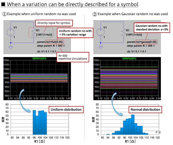
・Case in which variations can be directly described for symbols
In this example, a simulation is performed of the resistance value (voltage/current) when a voltage is applied to a 100 Ω resistor. The resistance value is written {100*(1+tol)}; this can be written directly in the resistance value field when setting the resistance value. A random number is used for tol to generate variation, and in this example the simulation is executed 300 times.
Two types of random number are used; the distributions of both are shown. In ①, the definition tol = flat(0.05) is used;
indicate a Gaussian random number with a standard deviation σ = 5%. Simulation results indicate a uniform distribution for the case in which the uniform random number was used, and a normal distribution for the case of the Gaussian random number.
・Case in which variations cannot be directly described for symbols
In a SPICE model, there are cases in which variations cannot be directly described for a symbol, as with the resistor above. The following is an example of simulation of the hFE-IC characteristic of an NPN bipolar transistor; because variations cannot be directly described for the bipolar transistor symbol, a method is used in which a description of the variation is added to the SPICE model.
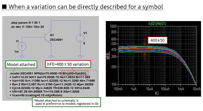
How to describe the variation is not the issue here, and so we omit the details of the description itself; in this simulator, however, a model is attached that adds a description of the parameter variation, hFE=400±50, for the bipolar transistor in the circuit diagram. This is the area surrounded by the green dashed line; descriptions of all parameters are given in addition to the parameter with the variation. The model lib includes a model for the 2SC4081 that does not include variation, but the model attached to the circuit diagram is used preferentially, and the results reflect the variation thus described.
What is important to understand the Monte Carlo setting method here is that there are cases in which the variation can be described directly for a symbol, such as a resistor, and that if this is not possible, there is a method for directly describing variation in the SPICE model.
Learn Know-how
Electrical Circuit Design
- Soldering Techniques and Solder Types
- Seven Tools for Soldering
- Seven Techniques for Printed Circuit Board Reworking
-
AC Circuits Fundamentals: Article Guide
- AC Circuits: Alternating Current, Waveforms, and Formulas
- Complex Numbers in AC Circuit
- Fundamentals of Capacitive Circuits: Understanding Series and Parallel Capacitor Connections
- Electrical Reactance
- What is Impedance? AC Circuit Analysis and Design
- Impedance Measurement: How to Choose Methods and Improve Accuracy
- Impedance Matching: Why It Matters for Power Transfer and Signal Reflections
- Resonant Circuits: Resonant Frequency and Q Factor
- RLC Circuit: Series and Parallel, Applied circuits
- What is AC Power? Active Power, Reactive Power, Apparent Power
- Power Factor: Calculation and Efficiency Improvement
- What is PFC?
- Boundary Current Mode (BCM) PFC: Examples of Efficiency Improvement Using Diodes
- Continuous Current Mode (CCM) PFC: Examples of Efficiency Improvement Using Diode
- LED Illumination Circuits:Example of Efficiency Improvement and Noise Reduction Using MOSFETs
- PFC Circuits for Air Conditioners:Example of Efficiency Improvement Using MOSFETs and Diodes
-
DC Circuits Fundamentals: Article Guide
- Ohm’s Law: Voltage, Current, and Resistance
- Electric Current and Voltage in DC Circuits
- Kirchhoff’s Circuit Laws
- What Is Mesh Analysis (Mesh Current Method)?
- What Is Nodal Analysis (Nodal Voltage Analysis)?
- Thevenin’s Theorem: DC Circuit Analysis
- Norton’s Theorem: Equivalent Circuit Analysis
- What Is the Superposition Theorem?
- What Is the Δ–Y Transformation (Y–Δ Transformation)?
- Voltage Divider Circuit
- Current Divider and the Current Divider Rule
Thermal design
-
About Thermal Design
- Changes in Engineering Trends and Thermal Design
- A Mutual Understanding of Thermal Design
- Fundamentals of Thermal Resistance and Heat Dissipation: About Thermal Resistance
- Fundamentals of Thermal Resistance and Heat Dissipation: Heat Transmission and Heat Dissipation Paths
- Fundamentals of Thermal Resistance and Heat Dissipation : Thermal Resistance in Conduction
- Fundamentals of Thermal Resistance and Heat Dissipation : Thermal Resistance in Convection
- Fundamentals of Thermal Resistance and Heat Dissipation : Thermal Resistance in Emission
- Thermal Resistance Data: JEDEC Standards, Thermal Resistance Measurement Environments, and Circuit Boards
- Thermal Resistance Data: Actual Data Example
- Thermal Resistance Data: Definitions of Thermal Resistance, Thermal Characterization Parameters
- Thermal Resistance Data: θJA and ΨJT in Estimation of TJ: Part 1
- Thermal Resistance Data: θJA and ΨJT in Estimation of TJ: Part 2
- Surface Temperature Measurements: Methods for Fastening Thermocouples
- Surface Temperature Measurements: Thermocouple Mounting Position
- Surface Temperature Measurements: Treatment of Thermocouple Tips
- Surface Temperature Measurements: Influence of the Thermocouple
- Estimating TJ: Basic Calculation Equations
- Estimating TJ: Calculation Example Using θJA
- Estimating TJ: Calculation Example Using ΨJT
- Estimating TJ: Calculation Example Using Transient Thermal Resistance
- Estimation of Heat Dissipation Area in Surface Mounting and Points to be Noted
- Surface Temperature Measurements: Thermocouple Types
- Summary
- Collection of Important Points Relating to Thermal Design
Switching Noise
- Procedures in Noise Countermeasures
- What is EMC?
-
Dealing with Noise Using Capacitors
- Understanding the Frequency Characteristics of Capacitors, Relative to ESR and ESL
- Measures to Address Noise Using Capacitors
- Effective Use of Decoupling (Bypass) Capacitors Point 1
- Effective Use of Decoupling Capacitors Point 2
- Effective Use of Decoupling Capacitors, Other Matters to be Noted
- Effective Use of Decoupling Capacitors, Summary
-
Dealing with Noise Using Inductors
- Frequency-Impedance Characteristics of Inductors and Determination of Inductor’s Resonance Frequency
- Basic Characteristics of Ferrite Beads and Inductors and Noise Countermeasures Using Them
- Dealing with Noise Using Common Mode Filters
- Points to be Noted: Crosstalk and Noise from GND Lines
- Summary of Dealing with Noise Using Inductors
- Other Noise Countermeasures
- Basics of EMC – Summary
Simulation
- Thermal Simulation of PTC Heaters
- Thermal Simulation of Linear Regulators
-
Foundations of Electronic Circuit Simulation Introduction
- About SPICE
- SPICE Simulators and SPICE Models
- Types of SPICE simulation: DC Analysis, AC Analysis, Transient Analysis
- Types of SPICE simulation: Monte Carlo
- Convergence Properties and Stability of SPICE Simulations
- Types of SPICE Model
- SPICE Device Models: Diode Example–Part 1
- SPICE Device Models: Diode Example–Part 2
- SPICE Subcircuit Models: MOSFET Example―Part 1
- SPICE Subcircuit Models: MOSFET Example―Part 2
- SPICE Subcircuit Models: Models Using Mathematical Expressions
- About Thermal Models
- About Thermal Dynamic Model
- Summary
-
About the ROHM Solution Simulator
- How to Access the ROHM Solution Simulator
- Trying Out the ROHM Solution Simulator (1)
- Trying Out the ROHM Solution Simulator (2)
- Starting a Simulation Circuit in the ROHM Solution Simulator
- ROHM Solution Simulator Toolbar Functions and Basic Operations
- ROHM Solution Simulator: User Interface
- Execution of Simulations
- Method for Displaying Simulation Results
- Simulation Result Display Tool: Wavebox
- Simulation Results Display Tool: Waveform Viewer
- Customization of Simulations
- Exporting Circuit Data to PartQuest™ Explorer
- Purchasing Samples for Evaluation
- Optimization of PFC Circuits
- Optimization of Inverter Circuits
- About Thermal Simulations of DC-DC Converters
- Circuit-Theory-Based Design Simulation