Learn Know-how
Estimating TJ: Calculation Example Using Transient Thermal Resistance
2022.12.21
Points of this article
・When a transient increase in power consumption is anticipated, the peak TJ in the transient state is sought.
・The transient thermal resistance is used for the thermal resistance when determining the temperature rise in a transient state.
・The peak TJ in the transient state should be checked to confirm that it does not exceed TJ MAX.
table of contents
Up until now, examples of calculations to estimate TJ when power consumption is constant have been presented. Here, however, a method of calculation and example are described for conditions in which there is a transient increase in power consumption.
Example of Transient Fluctuation
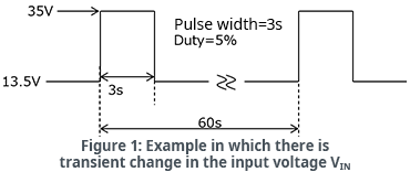
As the IC employed in the example, an LDO linear regulator is again used, the BD450M2EFJ-C. As the circuit conditions we consider a case in which the input voltage VIN undergoes transient fluctuation, as in Fig. 1. The steady-state input voltage is 13.5 V, but in this example the input voltage reaches 35 V for 3 seconds in a 60 second cycle.
As a result of transient fluctuation of the input voltage, the power consumption also fluctuates in a transient manner, and consequently it can easily be imagined that TJ will fluctuate as well. In such cases, the transient thermal resistance is used to calculate TJ by adding the transient temperature rise to the steady-state TJ.
About Transient Thermal Resistance
Strictly speaking, TJ rises (heat is generated) from the time power is input, and stabilizes after a certain time. The normal thermal resistance θJA is the value obtained by dividing the steady-state heat generation by the power consumption. On the other hand, the transient thermal resistance has a time-based parameter. In the example of Fig. 1, the transient thermal resistance is the value obtained by dividing the heat generation when VIN has changed from 13.5 V to 35 V and 3 seconds have elapsed by the changed power consumption.
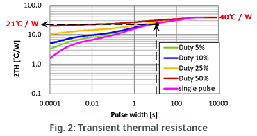
Fig. 2 shows a transient thermal resistance example. From the graph, the longer the time in the transient state (the longer the pulse width), the greater is the transient thermal resistance ZTH, and we see that when about 300 seconds have elapsed, the thermal resistance becomes constant.
Transient thermal resistance is often provided in graph form, and a value can be read off from the transient state time (pulse width). From the graph, the transient thermal resistance ZTH for the case of 3 seconds/cycle or a duty of 5% (green line) can be read off as 21°C/W. The steady-state value of 40°C/W is the value provided as θJA for the package.
An Example of Calculation to Estimate TJ Using Transient Thermal Resistance
As stated above, TJ is determined by adding the transient temperature rise calculated using the transient thermal resistance to the steady-state TJ. As the procedure used, first the steady-state and the transient power consumption values are calculated, and then the thermal resistance in each case is used to calculate the temperature rise (heat generation) for each. Then TA is added to the sum of the heat generation values for the steady state and for the transient state to determine the transient TJ. Let’s try performing the calculations.
We calculate the power consumption P1 for steady-state VIN=13.5 V, VOUT=5.0 V, IOUT=90 mA, and ICC=40 μA (typ).
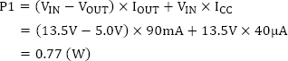
The power consumption P2 in the transient state with VIN=35 V is calculated. Keep in mind that P2 is a value that includes the steady-state power consumption P1=0.77 W.
![]()
Using the steady-state thermal resistance θJA=40℃/W and the transient thermal resistance ZTH (3s)=21℃/W for 3 seconds/5% duty, the respective TJ temperature increases are calculated. The transient temperature rise is calculated from the power consumption resulting by subtracting the steady-state power consumption P1 from P2.
Steady-state temperature increase ![]()
Transient temperature rise ![]()
These temperature increases are added to find the overall temperature increase.
Overall temperature increase ![]()
Finally, the ambient temperature TA in the transient state is added to determine TJ. Here TA is assumed to be 65°C.
In the transient state: ![]()
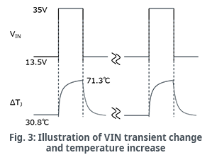
With this, we can find the maximum TJ under the condition that VIN of 13.5V transiently rises to 35V for 3s in a 60s period. Fig. 3 illustrates the temperature rise for the transient change in VIN. The temperature increase waveform is the VIN integrated waveform because the transient thermal resistance characteristic shown in Fig. 2 has a time-based parameter.
The purpose of the TJ calculations up to this point are to facilitate an understanding of the TJ peak when there is a transient increase in power consumption. Apart from this, there is also the approach of approximating TJ from the average power consumption. The following is a calculation example for the same conditions as those used above. As the thermal resistance, the steady-state thermal resistance θJA=40°C/W is employed.
Average power consumption ![]() ※0.05 is from Duty=5%.
※0.05 is from Duty=5%.
Average temperature rise ![]()
In the above calculations, the temperature rise during transient behavior is 71.3°C, and so we see that in this case, calculation using an average power consumption is not appropriate.
The most important thing to confirm in thermal calculations is whether or not TJ exceeds the absolute maximum rating TJ MAX. A surge above the absolute maximum rating is not allowed, even for a moment, and so the transient peak temperature must be determined.
If the transient state is sufficiently long (setting aside whether it should then be called “transient”), for example in the example of Fig. 2 in which the pulse width exceeds 300 seconds, the transient thermal resistance equals the steady-state thermal resistance. Hence it is sufficient to simply determine TJ under maximum power consumption for the steady-state thermal resistance, and confirm that this is less than TJ MAX.
【Download Documents】 Thermal Design of Semiconductor Components in Electronics
Thermal design has become a new issue in the design of electronic equipment in recent years, as thermal countermeasures have been the focus of attention. Although heat has been an important consideration for some time, the requirements for electronic equipment have changed in recent years, making it necessary to review conventional thermal countermeasures. This handbook describes thermal design based on the assumption that ICs and transistors are basically used in electronic equipment.

Learn Know-how
Electrical Circuit Design
- Soldering Techniques and Solder Types
- Seven Tools for Soldering
- Seven Techniques for Printed Circuit Board Reworking
-
AC Circuits Fundamentals: Article Guide
- AC Circuits: Alternating Current, Waveforms, and Formulas
- Complex Numbers in AC Circuit
- Fundamentals of Capacitive Circuits: Understanding Series and Parallel Capacitor Connections
- Electrical Reactance
- What is Impedance? AC Circuit Analysis and Design
- Impedance Measurement: How to Choose Methods and Improve Accuracy
- Impedance Matching: Why It Matters for Power Transfer and Signal Reflections
- Resonant Circuits: Resonant Frequency and Q Factor
- RLC Circuit: Series and Parallel, Applied circuits
- What is AC Power? Active Power, Reactive Power, Apparent Power
- Power Factor: Calculation and Efficiency Improvement
- What is PFC?
- Boundary Current Mode (BCM) PFC: Examples of Efficiency Improvement Using Diodes
- Continuous Current Mode (CCM) PFC: Examples of Efficiency Improvement Using Diode
- LED Illumination Circuits:Example of Efficiency Improvement and Noise Reduction Using MOSFETs
- PFC Circuits for Air Conditioners:Example of Efficiency Improvement Using MOSFETs and Diodes
-
DC Circuits Fundamentals: Article Guide
- Ohm’s Law: Voltage, Current, and Resistance
- Electric Current and Voltage in DC Circuits
- Kirchhoff’s Circuit Laws
- What Is Mesh Analysis (Mesh Current Method)?
- What Is Nodal Analysis (Nodal Voltage Analysis)?
- Thevenin’s Theorem: DC Circuit Analysis
- Norton’s Theorem: Equivalent Circuit Analysis
- What Is the Superposition Theorem?
- What Is the Δ–Y Transformation (Y–Δ Transformation)?
- Voltage Divider Circuit
- Current Divider and the Current Divider Rule
Thermal design
-
About Thermal Design
- Changes in Engineering Trends and Thermal Design
- A Mutual Understanding of Thermal Design
- Fundamentals of Thermal Resistance and Heat Dissipation: About Thermal Resistance
- Fundamentals of Thermal Resistance and Heat Dissipation: Heat Transmission and Heat Dissipation Paths
- Fundamentals of Thermal Resistance and Heat Dissipation : Thermal Resistance in Conduction
- Fundamentals of Thermal Resistance and Heat Dissipation : Thermal Resistance in Convection
- Fundamentals of Thermal Resistance and Heat Dissipation : Thermal Resistance in Emission
- Thermal Resistance Data: JEDEC Standards, Thermal Resistance Measurement Environments, and Circuit Boards
- Thermal Resistance Data: Actual Data Example
- Thermal Resistance Data: Definitions of Thermal Resistance, Thermal Characterization Parameters
- Thermal Resistance Data: θJA and ΨJT in Estimation of TJ: Part 1
- Thermal Resistance Data: θJA and ΨJT in Estimation of TJ: Part 2
- Surface Temperature Measurements: Methods for Fastening Thermocouples
- Surface Temperature Measurements: Thermocouple Mounting Position
- Surface Temperature Measurements: Treatment of Thermocouple Tips
- Surface Temperature Measurements: Influence of the Thermocouple
- Estimating TJ: Basic Calculation Equations
- Estimating TJ: Calculation Example Using θJA
- Estimating TJ: Calculation Example Using ΨJT
- Estimating TJ: Calculation Example Using Transient Thermal Resistance
- Estimation of Heat Dissipation Area in Surface Mounting and Points to be Noted
- Surface Temperature Measurements: Thermocouple Types
- Summary
- Collection of Important Points Relating to Thermal Design
Switching Noise
- Procedures in Noise Countermeasures
- What is EMC?
-
Dealing with Noise Using Capacitors
- Understanding the Frequency Characteristics of Capacitors, Relative to ESR and ESL
- Measures to Address Noise Using Capacitors
- Effective Use of Decoupling (Bypass) Capacitors Point 1
- Effective Use of Decoupling Capacitors Point 2
- Effective Use of Decoupling Capacitors, Other Matters to be Noted
- Effective Use of Decoupling Capacitors, Summary
-
Dealing with Noise Using Inductors
- Frequency-Impedance Characteristics of Inductors and Determination of Inductor’s Resonance Frequency
- Basic Characteristics of Ferrite Beads and Inductors and Noise Countermeasures Using Them
- Dealing with Noise Using Common Mode Filters
- Points to be Noted: Crosstalk and Noise from GND Lines
- Summary of Dealing with Noise Using Inductors
- Other Noise Countermeasures
- Basics of EMC – Summary
Simulation
- Thermal Simulation of PTC Heaters
- Thermal Simulation of Linear Regulators
-
Foundations of Electronic Circuit Simulation Introduction
- About SPICE
- SPICE Simulators and SPICE Models
- Types of SPICE simulation: DC Analysis, AC Analysis, Transient Analysis
- Types of SPICE simulation: Monte Carlo
- Convergence Properties and Stability of SPICE Simulations
- Types of SPICE Model
- SPICE Device Models: Diode Example–Part 1
- SPICE Device Models: Diode Example–Part 2
- SPICE Subcircuit Models: MOSFET Example―Part 1
- SPICE Subcircuit Models: MOSFET Example―Part 2
- SPICE Subcircuit Models: Models Using Mathematical Expressions
- About Thermal Models
- About Thermal Dynamic Model
- Summary
-
About the ROHM Solution Simulator
- How to Access the ROHM Solution Simulator
- Trying Out the ROHM Solution Simulator (1)
- Trying Out the ROHM Solution Simulator (2)
- Starting a Simulation Circuit in the ROHM Solution Simulator
- ROHM Solution Simulator Toolbar Functions and Basic Operations
- ROHM Solution Simulator: User Interface
- Execution of Simulations
- Method for Displaying Simulation Results
- Simulation Result Display Tool: Wavebox
- Simulation Results Display Tool: Waveform Viewer
- Customization of Simulations
- Exporting Circuit Data to PartQuest™ Explorer
- Purchasing Samples for Evaluation
- Optimization of PFC Circuits
- Optimization of Inverter Circuits
- About Thermal Simulations of DC-DC Converters
- Circuit-Theory-Based Design Simulation