
Learn Know-how
What Is a Bypass Capacitor? Uses, Values, and Placement
A bypass capacitor is a capacitor used in electronic circuits to keep the power supply stable by diverting, or "bypassing," noise to ground. It is also called a decoupling capacitor. Its purposes are to remove high-frequency noise, stabilize the supply voltage, and supply supplemental charge to ICs, thereby improving the reliability and performance of electronic equipment. When a bypass capacitor with an appropriate capacitance value is selected and placed correctly, the circuit is protected from external noise and operates stably. Bypass capacitors play an important role in the noise control and stability of electronic equipment. This article explains the roles of bypass capacitors, how to choose the optimal capacitance, and the key points for connecting them.
Roles of a Bypass Capacitor
What is a bypass capacitor?
A bypass capacitor is a capacitor connected between the power supply and ground (GND) that diverts, or bypasses, noise away from the circuit. The term does not refer to a specific type of capacitor; it is a general name for any capacitor used to bypass noise. By diverting noise, it enables a stable supply of power to the electronic circuit.
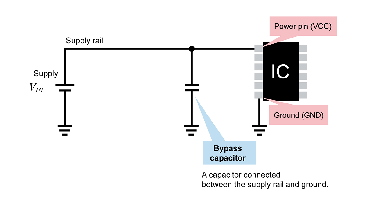
Bypass capacitors are important enough that some electronic circuits cannot operate correctly without them.
A bypass capacitor separates the AC components, such as noise, from the DC supply voltage and diverts them to ground. Because it decouples these unwanted AC components from the DC supply, it is also called a decoupling capacitor.
Bypass capacitors are used to suppress high-frequency noise and to stabilize the supply voltage. The capacitance depends on the purpose: roughly several hundred pF to 0.01 μF for high-frequency noise suppression, and several tens of μF to several hundred μF for supply voltage stabilization.
The three roles of a bypass capacitor
Let's look at the roles of a bypass capacitor in more detail. It has three roles: suppressing high-frequency noise, stabilizing the supply voltage, and supplying supplemental charge to the IC as a local power source.
Suppressing high-frequency noise
A bypass capacitor lowers the impedance between the supply rail and ground, so that high-frequency noise entering the supply rail is shunted to ground and removed.
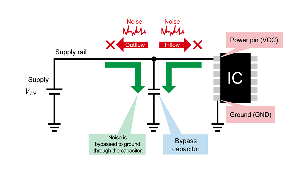
To absorb high-frequency noise, a capacitor with a small capacitance of about several hundred pF to 0.01 μF is used.
A small-capacitance bypass capacitor cannot absorb noise effectively unless it is placed close to the noise source. For this reason, it is placed as close as possible to the IC's power pin.
Reducing supply voltage fluctuations
A bypass capacitor also suppresses fluctuations in the supply voltage by releasing the charge it has stored.
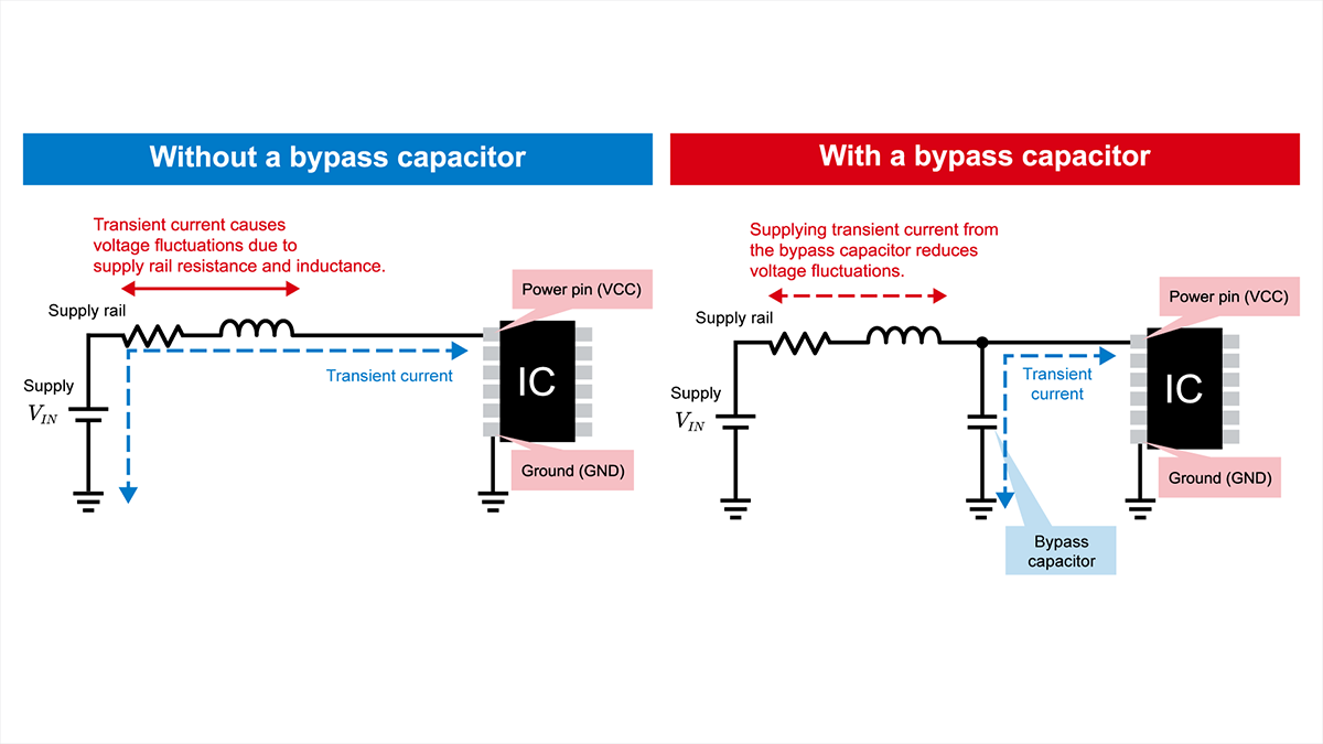
Without a bypass capacitor, when a transient current flows, the resistance and inductance present in the supply rail cause the voltage to fluctuate. These voltage fluctuations can cause equipment to malfunction and can also become a source of radiated noise.
With a bypass capacitor in place, the transient current is supplied by the bypass capacitor, which keeps voltage fluctuations on the supply rail small. This prevents malfunction and radiated noise.
Supplying supplemental charge to the IC as a local power source
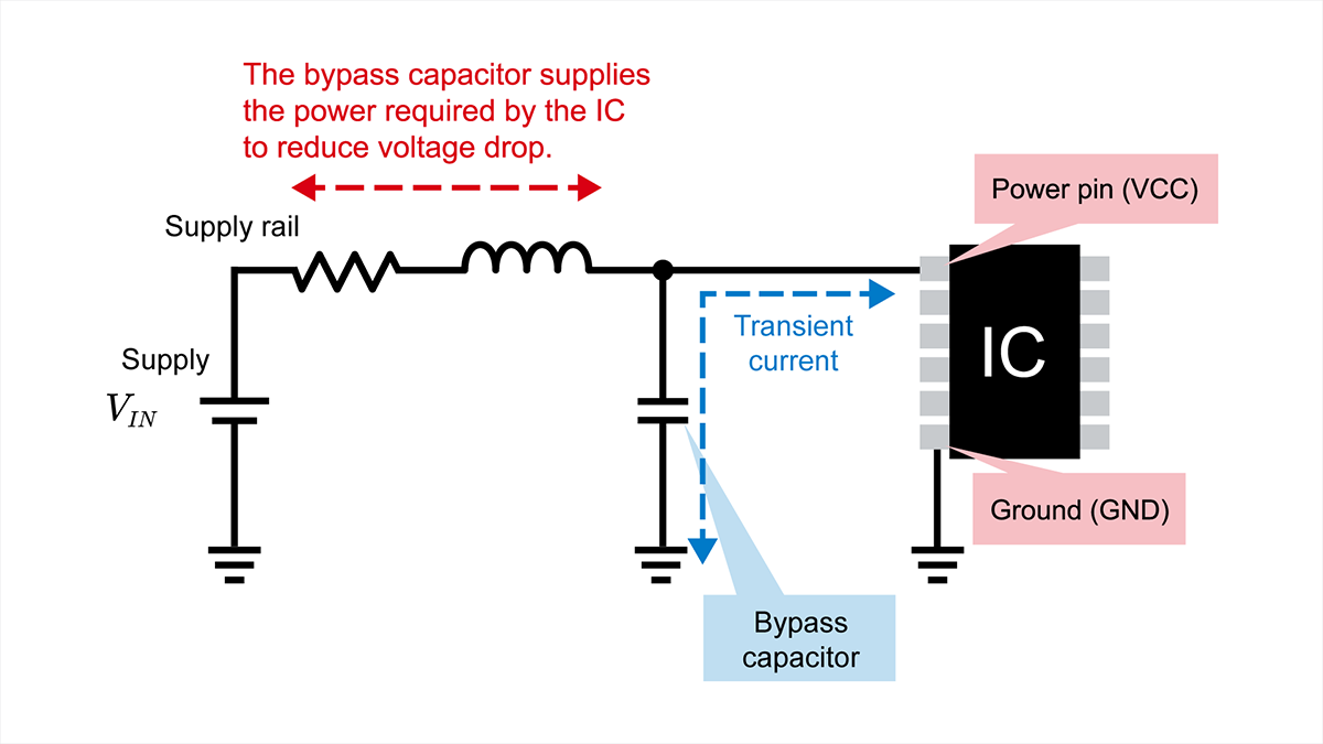
A bypass capacitor also supplies charge to the IC to make up for any shortfall in the power it needs. When the IC's current consumption increases suddenly, the inductance of the supply path may prevent enough current from being delivered in time. In such cases, the charge discharged from the bypass capacitor serves as the transient current, preventing faults.
However, the amount of charge a capacitor can store is limited, so a component with sufficient capacitance is required for it to serve as a local power source.
As described above, a bypass capacitor is an extremely important component for maintaining a stable supply voltage. Without one, the supply rail may become unstable and the IC may not operate correctly.
Where to Place a Bypass Capacitor
Place it close to the power pin
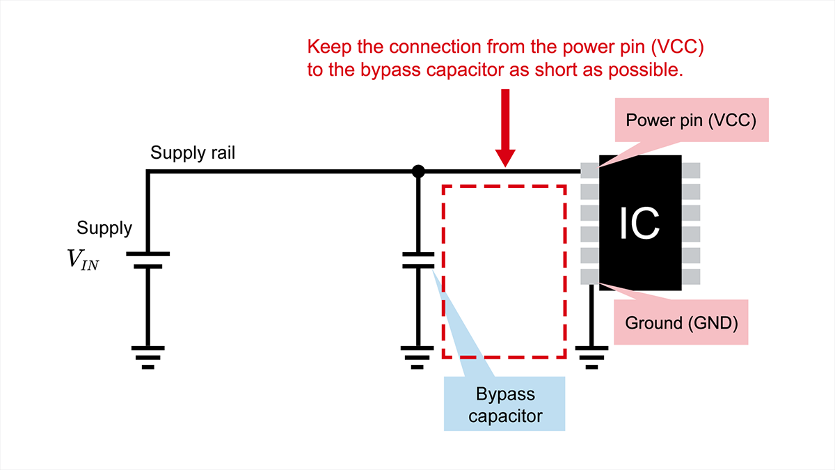
To remove high-frequency noise, place the bypass capacitor as close as possible to the IC's power pin. If the IC and the capacitor are far apart, the inductance of the wiring between them increases, reducing the noise removal effect.
Placing the bypass capacitor close to the IC also shortens the loop through which the noise current flows, which helps suppress radiated noise. During PCB layout, always place the bypass capacitor close to the IC's power pin.
Place smaller capacitors closer to the power pin
When connecting multiple bypass capacitors, place the capacitor with the smallest capacitance closest to the power pin. For example, arrange them as power pin ← 0.01 μF ← 0.1 μF ← 1 μF, so that the capacitance increases with distance from the pin. If this order is reversed, high-frequency noise becomes harder to remove.
Capacitors with larger capacitance are less affected by distance, so they can be placed farther from the IC's power pin without problems.
Choose the capacitance with the noise frequency in mind
As explained above, the capacitance of a bypass capacitor depends on its purpose: several hundred pF to 0.01 μF for high-frequency noise suppression, and several tens of μF to several hundred μF for supply voltage stabilization.
However, the impedance-versus-frequency characteristic of a capacitor also changes with its capacitance, so the frequency of the noise must be taken into account as well.
For high-frequency noise, a small capacitance of several hundred pF to 0.01 μF is more effective because its higher self-resonant frequency gives it lower impedance at those frequencies. For low-frequency noise, a large capacitance of 10 μF or more is required to absorb the noise.
When the noise to be removed spans a wide frequency range, use a combination of capacitors with different capacitance values.
Capacitance of a Bypass Capacitor
The capacitance of a bypass capacitor is selected according to the frequency of the noise to be removed. Let's look at the frequency characteristics of a capacitor.
A capacitor has not only capacitance (C) but also equivalent series resistance (ESR), determined by dielectric loss and electrode resistance, and equivalent series inductance (ESL), determined by the inductance of the electrodes.
Because of these parasitic elements, the impedance-versus-frequency characteristic is V-shaped, turning upward above the self-resonant frequency. The lower the impedance of the bypass capacitor, the better its noise suppression performance.
How to determine the capacitance of a bypass capacitor
A bypass capacitor with lower capacitance has a higher self-resonant frequency, where its impedance reaches its minimum, so it is more effective against high-frequency noise. Because power supply noise arises from the IC's switching operation, the appropriate capacitance value is determined by the IC's operating frequency.
For example, for low-frequency noise such as that from a switching power supply circuit, a large-capacitance capacitor (several tens to several hundred μF) is the better choice. To reduce high-frequency noise generated by an IC operating at several tens of MHz or higher, use a small-capacitance capacitor of about several hundred pF to 0.01 μF.
When a datasheet is available
The datasheets of some components, such as power supply ICs, include a recommended circuit that specifies the bypass capacitors. When a datasheet is available, some designers simply adopt what it specifies.
Even so, it is important to read the datasheet carefully and understand why a capacitor of that particular capacitance is used.
Many datasheets show circuits that combine several bypass capacitors. The next section explains the use of multiple bypass capacitors.
Number of Bypass Capacitors
Several bypass capacitors are sometimes connected in parallel, for example when noise across a wide frequency range must be addressed. The effect depends on whether the capacitors have the same or different capacitances.
When using several capacitors of different capacitances, place the smaller-capacitance capacitor closer to the IC, as described earlier.
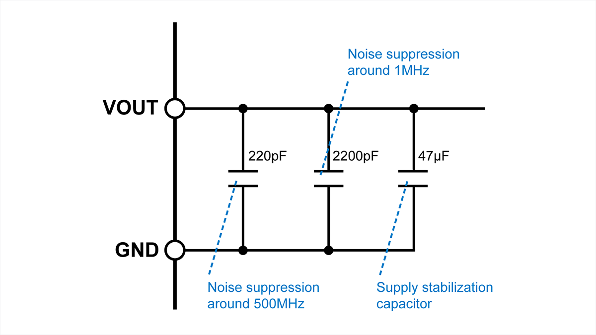
The small-capacitance capacitor lowers the impedance at high frequencies and the large-capacitance capacitor lowers it at low frequencies, so the combination is effective over a wide frequency band.
Conversely, when several capacitors of the same capacitance are connected in parallel, the impedance falls across the entire frequency range, and it falls further as more capacitors are added. This provides greater noise suppression.
Combining several bypass capacitors improves noise suppression, but it also takes up more board space. Connect them only where noise suppression is needed.
Precautions When Using Bypass Capacitors
Watch out for DC bias characteristics in ceramic capacitors
Bypass capacitors are often used in combinations of several types. One of these, the ceramic capacitor, exhibits a DC bias characteristic: its capacitance decreases when a DC voltage is applied.
The capacitance specified for a ceramic capacitor is a nominal value. When a DC voltage is applied, the actual capacitance drops below the nominal value, creating a gap between the nominal and effective capacitance in the circuit.
When using ceramic capacitors, choose one with a rated voltage several times the applied voltage to minimize capacitance loss due to DC bias.
Watch out for anti-resonance with different capacitance values
When capacitors of different capacitances are connected in parallel, anti-resonance can occur, causing the power supply impedance to rise. When anti-resonance occurs, the supply voltage can change significantly, and as a result the IC may malfunction.
To reduce anti-resonance, consider changing the combination of capacitance values or adding or removing bypass capacitors.
Summary
A bypass capacitor is connected between the power supply and ground, supplying supplemental charge to the IC while filtering out high-frequency noise. It also suppresses supply voltage fluctuations, preventing equipment malfunctions and failures.
For a bypass capacitor to fully perform these roles, correct placement is essential: place it as close as possible to the IC's power pin. Also keep in mind that applying a DC voltage to a ceramic capacitor reduces its effective capacitance, and that combining capacitors of different capacitance values can cause anti-resonance.
Use the points above as a reference when applying bypass capacitors in your designs.
【Download Documents】 Switching Power Supply Basic of EMC and Noise Countermeasures
This is a handbook on the basics of EMC (electromagnetic compatibility) and noise countermeasures for switching power supplies. Based on the understanding of the basics of noise, it explains the noise countermeasures using capacitors and inductors in switching power supplies.

Learn Know-how
Electrical Circuit Design
- Soldering Techniques and Solder Types
- Seven Tools for Soldering
- Seven Techniques for Printed Circuit Board Reworking
-
AC Circuits Fundamentals: Article Guide
- AC Circuits: Alternating Current, Waveforms, and Formulas
- Complex Numbers in AC Circuit
- Fundamentals of Capacitive Circuits: Understanding Series and Parallel Capacitor Connections
- Electrical Reactance
- What is Impedance? AC Circuit Analysis and Design
- Impedance Measurement: How to Choose Methods and Improve Accuracy
- Impedance Matching: Why It Matters for Power Transfer and Signal Reflections
- Resonant Circuits: Resonant Frequency and Q Factor
- RLC Circuit: Series and Parallel, Applied circuits
- What is AC Power? Active Power, Reactive Power, Apparent Power
- Power Factor: Calculation and Efficiency Improvement
- What is PFC?
- Boundary Current Mode (BCM) PFC: Examples of Efficiency Improvement Using Diodes
- Continuous Current Mode (CCM) PFC: Examples of Efficiency Improvement Using Diode
- LED Illumination Circuits:Example of Efficiency Improvement and Noise Reduction Using MOSFETs
- PFC Circuits for Air Conditioners:Example of Efficiency Improvement Using MOSFETs and Diodes
-
DC Circuits Fundamentals: Article Guide
- Electric Current and Voltage in DC Circuits
- Ohm’s Law: Voltage, Current, and Resistance
- Series Circuit Calculator for Resistance, Current, Voltage Drop, and Power
- Parallel Resistor Calculator for Equivalent Resistance, Branch Current, and Power
- Kirchhoff’s Circuit Laws
- What Is Mesh Analysis (Mesh Current Method)?
- What Is Nodal Analysis (Nodal Voltage Analysis)?
- Thevenin’s Theorem: DC Circuit Analysis
- Norton’s Theorem: Equivalent Circuit Analysis
- What Is the Superposition Theorem?
- What Is the Δ–Y Transformation (Y–Δ Transformation)?
- Voltage Divider Circuit
- Current Divider and the Current Divider Rule
Thermal design
-
About Thermal Design
- Changes in Engineering Trends and Thermal Design
- A Mutual Understanding of Thermal Design
- Fundamentals of Thermal Resistance and Heat Dissipation: About Thermal Resistance
- Fundamentals of Thermal Resistance and Heat Dissipation: Heat Transmission and Heat Dissipation Paths
- Fundamentals of Thermal Resistance and Heat Dissipation : Thermal Resistance in Conduction
- Fundamentals of Thermal Resistance and Heat Dissipation : Thermal Resistance in Convection
- Fundamentals of Thermal Resistance and Heat Dissipation : Thermal Resistance in Emission
- Thermal Resistance Data: JEDEC Standards, Thermal Resistance Measurement Environments, and Circuit Boards
- Thermal Resistance Data: Actual Data Example
- Thermal Resistance Data: Definitions of Thermal Resistance, Thermal Characterization Parameters
- Thermal Resistance Data: θJA and ΨJT in Estimation of TJ: Part 1
- Thermal Resistance Data: θJA and ΨJT in Estimation of TJ: Part 2
- Surface Temperature Measurements: Methods for Fastening Thermocouples
- Surface Temperature Measurements: Thermocouple Mounting Position
- Surface Temperature Measurements: Treatment of Thermocouple Tips
- Surface Temperature Measurements: Influence of the Thermocouple
- Estimating TJ: Basic Calculation Equations
- Estimating TJ: Calculation Example Using θJA
- Estimating TJ: Calculation Example Using ΨJT
- Estimating TJ: Calculation Example Using Transient Thermal Resistance
- Estimation of Heat Dissipation Area in Surface Mounting and Points to be Noted
- Surface Temperature Measurements: Thermocouple Types
- Summary
- Collection of Important Points Relating to Thermal Design
Switching Noise
- Procedures in Noise Countermeasures
- What is EMC?
-
Dealing with Noise Using Capacitors
- Understanding the Frequency Characteristics of Capacitors, Relative to ESR and ESL
- Measures to Address Noise Using Capacitors
- What Is a Bypass Capacitor? Uses, Values, and Placement
- Effective Use of Decoupling Capacitors Point 1
- Effective Use of Decoupling Capacitors Point 2
- Effective Use of Decoupling Capacitors, Other Matters to be Noted
- Effective Use of Decoupling Capacitors, Summary
-
Dealing with Noise Using Inductors
- Frequency-Impedance Characteristics of Inductors and Determination of Inductor’s Resonance Frequency
- Basic Characteristics of Ferrite Beads and Inductors and Noise Countermeasures Using Them
- Dealing with Noise Using Common Mode Filters
- Points to be Noted: Crosstalk and Noise from GND Lines
- Summary of Dealing with Noise Using Inductors
- Other Noise Countermeasures
- Basics of EMC – Summary
Simulation
- Thermal Simulation of PTC Heaters
- Thermal Simulation of Linear Regulators
-
Foundations of Electronic Circuit Simulation Introduction
- About SPICE
- SPICE Simulators and SPICE Models
- Types of SPICE simulation: DC Analysis, AC Analysis, Transient Analysis
- Types of SPICE simulation: Monte Carlo
- Convergence Properties and Stability of SPICE Simulations
- Types of SPICE Model
- SPICE Device Models: Diode Example–Part 1
- SPICE Device Models: Diode Example–Part 2
- SPICE Subcircuit Models: MOSFET Example―Part 1
- SPICE Subcircuit Models: MOSFET Example―Part 2
- SPICE Subcircuit Models: Models Using Mathematical Expressions
- About Thermal Models
- About Thermal Dynamic Model
- Summary
-
About the ROHM Solution Simulator
- How to Access the ROHM Solution Simulator
- Trying Out the ROHM Solution Simulator (1)
- Trying Out the ROHM Solution Simulator (2)
- Starting a Simulation Circuit in the ROHM Solution Simulator
- ROHM Solution Simulator Toolbar Functions and Basic Operations
- ROHM Solution Simulator: User Interface
- Execution of Simulations
- Method for Displaying Simulation Results
- Simulation Result Display Tool: Wavebox
- Simulation Results Display Tool: Waveform Viewer
- Customization of Simulations
- Exporting Circuit Data to PartQuest™ Explorer
- Purchasing Samples for Evaluation
- Optimization of PFC Circuits
- Optimization of Inverter Circuits
- About Thermal Simulations of DC-DC Converters
- Circuit-Theory-Based Design Simulation